
Heat sink built in cavity cylindrical light emitting diode wick

A technology of light-emitting diodes and cooling devices, applied in the field of light sources, can solve the problems of not being able to take away heat, affecting the service life of wicks, and easy burning of light-emitting diodes, so as to achieve the effect of improving heat dissipation efficiency and high reliability

Active Publication Date: 2011-09-21
广州朗辰伟烨照明科技有限公司
View PDF0 Cites 0 Cited by
  • Summary
  • Abstract
  • Description
  • Claims
  • Application Information

AI Technical Summary

Problems solved by technology

[0005] However, the ideal heat dissipation method in the market is to install an electric fan at the opening of the wick, and use the electric fan to blow air inward against the opening, and then the hot air is discharged from the other end of the opening. Although this heat dissipation method has a certain heat dissipation effect on the wick, But there are still deficiencies, mainly in the entrance and the middle of the light-emitting diodes are effectively cooled due to the heat dissipation effect of the fresh cold wind, but because the heat is absorbed in the front, when the wind reaches the vicinity of the exit, the light-emitting diodes at this place cannot be turned off. The heat generated is taken away, causing the LEDs closer to the outlet to burn out more easily, which affects the service life of the wick

Method used


Image

  • Heat sink built in cavity cylindrical light emitting diode wick
  • Heat sink built in cavity cylindrical light emitting diode wick
  • Heat sink built in cavity cylindrical light emitting diode wick

Examples


Embodiment 1

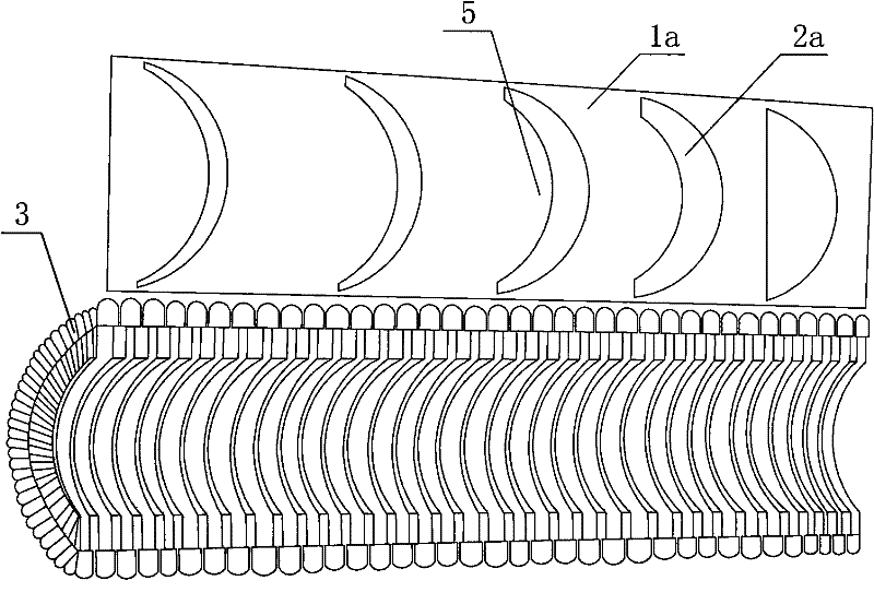
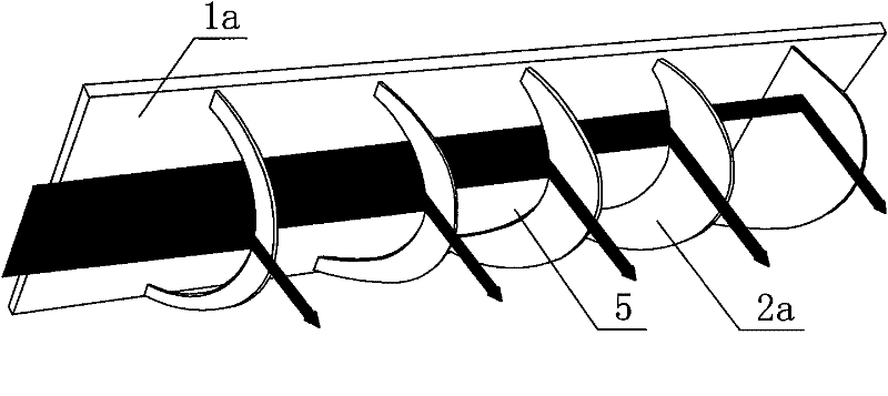
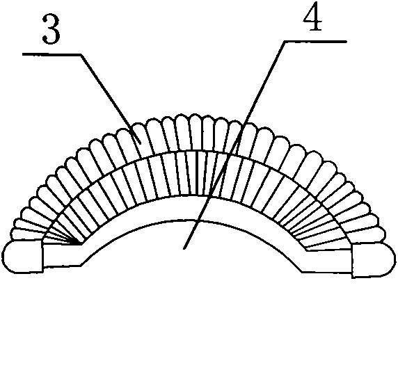
[0028] The light-emitting diode wick 3 of this embodiment is semi-cylindrical, and the fixture and blade structure placed in its chamber 4 are as follows: figure 1 , figure 2 As shown, the fixing part is a bakelite fixing plate 1a of suitable specifications, on which five reflective arc-shaped blades 2a are arranged, and the arc-shaped blades 2a are sequentially For the first, second, third, fourth and fifth blades, the area of ​​the opening 5 at the root of the first blade is the largest, and the area of ​​the blade is the smallest, followed by the second, and so on, and the end blade has no opening , into a completely closed shape, when a beam of uniform heat dissipation medium with a certain pressure passes through the first blade, part of the heat dissipation medium is reflected by the blade to dissipate heat for the LED corresponding to the section of the wick, and the rest of the heat dissipation medium is from the The lower part of the first blade passes through, and ...

Embodiment 2

[0031] According to the same principle, LED wicks of various shapes can also be manufactured. Such as Figure 7 The light-emitting diode wick 3 shown is in the shape of a quadrangular prism, and the corresponding fixing part is a shelf 1b with an X-shaped cross-section. Each unit chamber 4 of the X-shaped shelf 1b is respectively provided with the plurality of reflective blades 2b . The X-shaped frame 1b is built in the quadrangular prism light-emitting diode wick 3, then constitutes Figure 9 The quadrangular prism LED wick shown, from Figure 8 It can be seen that when a heat dissipation medium that is uniform and has a certain pressure enters the quadrangular prism light-emitting diode wick 3, the heat dissipation medium is divided into four equal parts, and when each part of the medium passes through the blades of each zone, it is divided into four equal parts. The set number of reflective mediums for each blade can give the light emitting diodes of each segment surface...


PUM


Abstract

The invention discloses a heat sink built in a cavity cylindrical light emitting diode wick, comprising a cylindrical wick with a cavity therein. The cavity of the cylindrical wick therein is provided with a fastener, multiple reflection blades are distantly arranged in the length direction of the fastener, the roots of a first reflection blade to a last but one radiating fin are provided with openings, and the opening areas are decreased in sequence, and the last fin is not provided with an opening. The number of the radiating media needed by the light emitting diodes corresponding to each section of the wick is determined according to the reflecting action of the reflection blades, so as to determine the sizes of the openings at the roots of the radiating media blades and the inclination angle of each blade, such that each light emitting diode of the whole wick obtains relatively uniform radiating effect. As the radiating media blades at each section of the wick are parallel radiating structures, the invention relatively excellently solves the heat superposition and heat internal circulation in the wick, so as to decrease the radiating effect of the wick and improve radiating efficiency.

Description

Technical field: [0001] The invention relates to the technical field of light sources, in particular to a high-intensity wick special-purpose cooling device using a plurality of small-power (0.06 watts each) light-emitting diodes as illuminants. Background technique: [0002] The lamps made of dense strong light wicks through suitable optical reflectors (lampshades) can be widely used in searchlights, motor vehicle headlights and night lights for streets, roads, bridges or squares, etc. At present, high-intensity strong light is being produced For high-pressure lamps, the wicks of metal halide lamps or high-pressure sodium lamps are often used as light sources. The power of these lamps is generally about 100-1000 watts. A lamp using a metal halide wick or a high-pressure sodium wick as a light source has the characteristics of good light intensity and low production cost, but its service life is generally about thousands of hours, and its electro-optical conversion efficienc...

Claims


Application Information

Patent Timeline
Patent Type & Authority Patents(China)
IPC IPC(8): F21V7/10F21Y101/02H01L23/367F21V29/00F21V29/508F21V29/71F21Y115/10
Inventor 梁允生
Owner 广州朗辰伟烨照明科技有限公司
Learn More