
District cooling type ice-storage tank device

A technology of partitioned cooling and ice storage tanks, which is applied to the types of heat exchangers, heating methods, fixed conduit components, etc., can solve problems such as difficult uniform heat transfer, compressor liquid compression, and low heat transfer efficiency of coils, and achieve Uniform heat, uniform temperature, avoiding the effect of liquid accumulation in the tube

Inactive Publication Date: 2010-12-08
GUANGDONG CHIGO AIR CONDITIONING
View PDF1 Cites 1 Cited by
  • Summary
  • Abstract
  • Description
  • Claims
  • Application Information

AI Technical Summary

Problems solved by technology

[0002] The invention patent with the application number 200710040993.5 mentions an ice storage tank used in a large-scale cold storage air conditioning system. The heat exchange coil in the tank is designed as a serpentine tube with a U-line horizontal parallel flow path, and there are no other related supports in the tank. Or baffle-like structural parts, during the solidification process, the water will have a layered distribution of water temperature at low temperatures (that is, the upper water temperature is low, the lower water temperature is high), it is difficult to achieve uniform freezing of the water in the entire ice storage tank, and local local freezing occurs. Difficulty in freezing or melting ice
At the same time, due to the horizontal arrangement of the heat exchange coil, affected by gravity, the heat transfer between the refrigerant flowing in the tube and the water outside the tube during the evaporation process is uneven, and liquid accumulation is easy to occur in the second half of the tube, so the heat exchange efficiency of the coil Low, it is difficult to obtain the effect of uniform heat exchange, and it is easy to cause the liquid compression of the compressor, which affects the life of the main refrigeration unit

Method used


Image

  • District cooling type ice-storage tank device
  • District cooling type ice-storage tank device

Examples


Embodiment Construction

[0012] In order to make the above objects, features and advantages of the present invention more comprehensible, the present invention will be further described in detail below in conjunction with the accompanying drawings and specific embodiments.

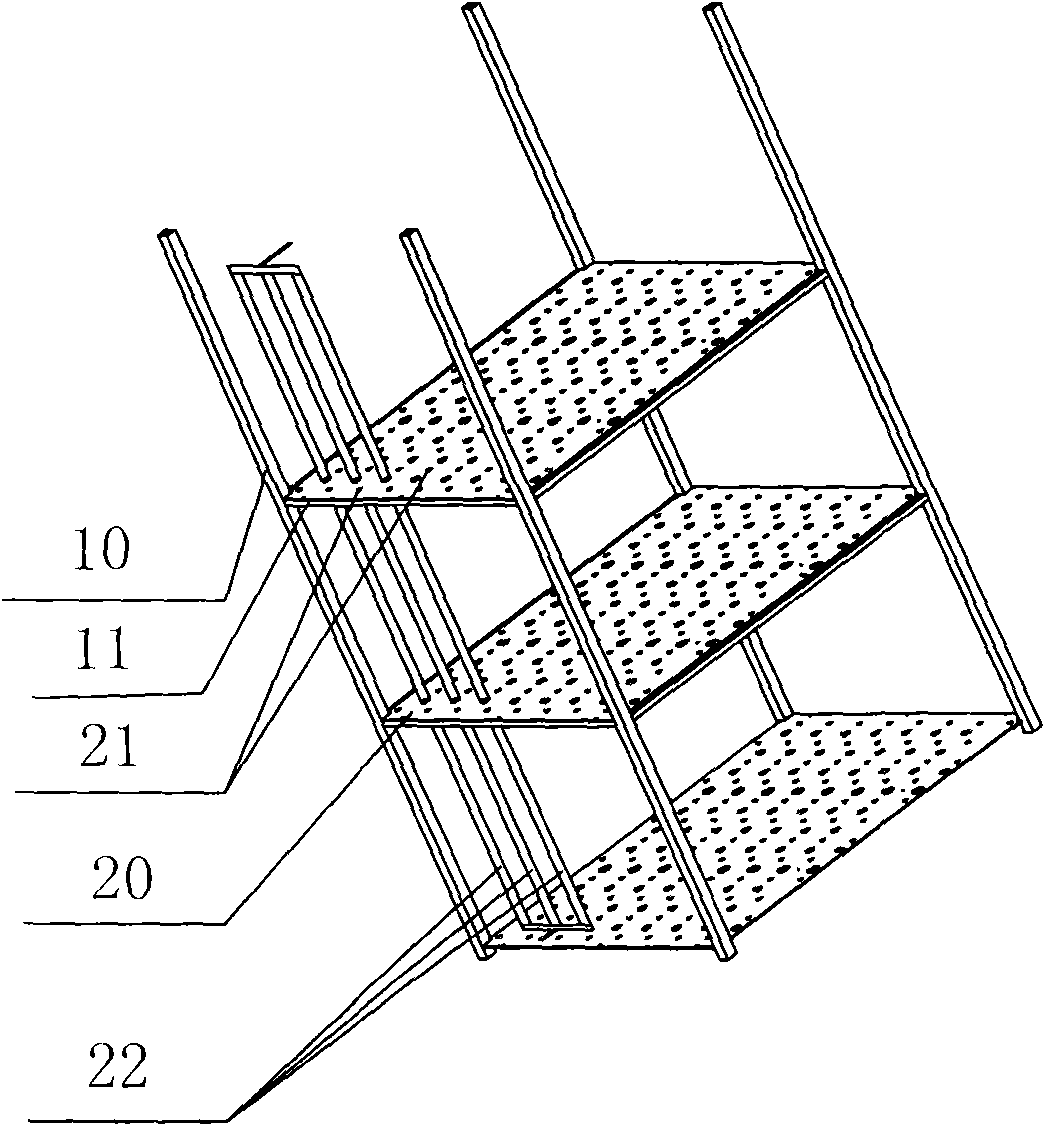
[0013] refer to figure 1 , the partition cooling type ice storage device of the present invention is aimed at the phenomenon that water is prone to produce a large temperature difference between the upper and lower sides during the process of solidification and dissolution at low temperatures. There are heat exchange coils and brackets in the ice storage tank, and the brackets include four columns 10 And vertically connected with the column 10, a plurality of partitions 11 arranged at intervals of 30 to 50 cm at equal or unequal intervals, as can be seen from the figure, four columns 10 are arranged at the four corners of the partition 11, and each partition 11 A heat conduction plate 20 is provided on the heat conduction plate 20...


PUM


Abstract

A district cooling type ice-storage tank device comprises a heat-exchanging coil; a bracket is arranged in an ice-storage tank; a plurality of layers of heat-conducting panels are arranged on the bracket along the water surface direction; through holes are evenly designed in the heat-conducting panels for conducting heat exchange between the water at the upper layer and the lower layer; the heat-exchanging coil is inserted in a layer frame structure and the heat-conducting panels; and the heat-conducting panels are vertical to the flow direction of refrigerant in the heat-exchanging coil. As the heat-conducting panels are additionally arranged to conduct incomplete fault segmentation to the water body, on one hand, the temperature difference between the upper water layer and the lower water layer adjacent to the heat-conducting panels at the enhancing layers is reduced; on the other hand, the through holes in the heat-conducting panels can lead the high-temperature water at the bottomof the upper layer thereof and the low-temperature water on the top of the lower layer to be effectively diffused and convected, thereby ensuring the temperature at the upper water layer and the lowerwater layer to be more uniform. In addition, by adopting a vertical heat-exchanging coil with an isometric or unequally spaced design layout to form subsection heat exchange, the heat-exchanging amount at each section at a certain height can be ensured basically the same, and the liquid accumulated in a tube can be effectively avoided, thereby leading the heat exchange to be more uniform.

Description

technical field [0001] The invention relates to a cold storage device, more precisely, an ice cold storage device for refrigeration and air conditioning. Background technique [0002] The invention patent with the application number 200710040993.5 mentions an ice storage tank used in a large-scale cold storage air conditioning system. The heat exchange coil in the tank is designed as a serpentine tube with a U-line horizontal parallel flow path, and there are no other related supports in the tank. Or baffle-like structural parts, during the solidification process, the water will have a layered distribution of water temperature at low temperatures (that is, the upper water temperature is low, the lower water temperature is high), it is difficult to achieve uniform freezing of the water in the entire ice storage tank, and local local freezing occurs. A phenomenon in which ice or ice is difficult to melt. At the same time, due to the horizontal arrangement of the heat exchange...

Claims


Application Information

Patent Timeline
Patent Type & Authority Patents(China)
IPC IPC(8): F28D1/04F28F13/00F28F9/007F24F5/00
Inventor 施永康陈颖
Owner GUANGDONG CHIGO AIR CONDITIONING
Learn More