Deep ultraviolet projection lithographic objective

A projection light and deep ultraviolet technology, applied in the direction of microlithography exposure equipment, optics, optical components, etc., can solve the problems of difficulty in making ultra-fine masks, small optical reduction magnification, and high price, so as to simplify the production of objective lenses and reduce The effect of production cost and difficulty reduction

Inactive Publication Date: 2010-09-22
INST OF OPTICS & ELECTRONICS - CHINESE ACAD OF SCI
View PDF5 Cites 0 Cited by
  • Summary
  • Abstract
  • Description
  • Claims
  • Application Information

AI Technical Summary

Problems solved by technology

The existing deep ultraviolet (193nm) projection lithography objective lenses disclosed by companies such as Nikon, Canon, Zeiss, Tropel, etc., have numerical apertures greater than or equal to 0.50-0.60, and can resolve The power is also very high; but these objective lenses are complex in structure and expensive, and cannot be manufactured by general units, nor can they afford it. At the same time, due to the small optical reduction magnification, it is difficult to make ultra-fine masks
In the existing projection lithography objective lens, there are no various new resolution enhancement devices such as light addition and subtraction, phase matching and polarization superposition, and only have the traditional optical limit resolution.

Method used


Image

  • Deep ultraviolet projection lithographic objective
  • Deep ultraviolet projection lithographic objective
  • Deep ultraviolet projection lithographic objective

Examples


Embodiment Construction

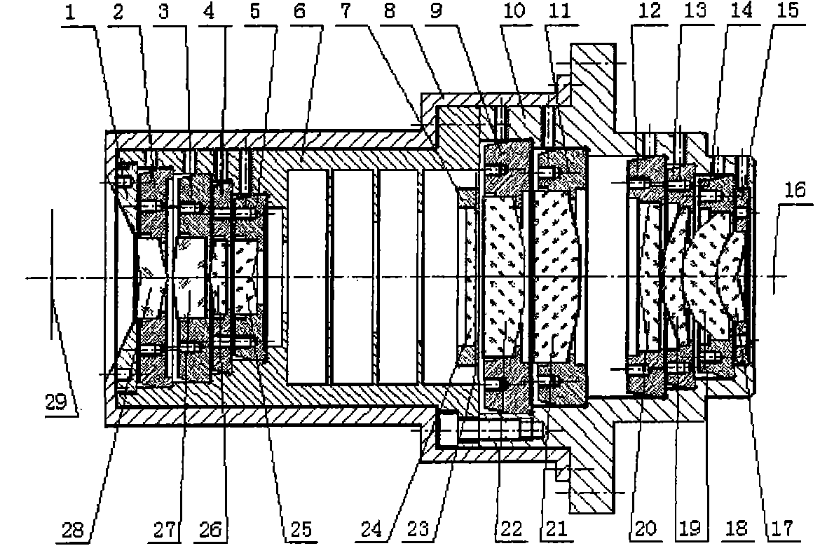
[0026] Such as figure 1 As shown, Embodiment 1 of the present invention includes a three-layer structure of a thermostatic jacket 8, an intermediate layer, an optical lens element and a lens frame assembly. The constant temperature jacket 8 with the clean circulating water of precise constant temperature is the outer layer of the deep ultraviolet projection lithography objective lens. The thermostatic overcoat 8 is sealed outside the lens barrel. The constant temperature coat 8 keeps the temperature of the lens barrel and the optical lens frame assembly, and also separates the optical lens elements in the lens barrel and the space between the elements from the outside atmosphere.

[0027] The middle layer is the lens barrel, which is formed by connecting the first lens barrel 6 and the second lens barrel 10 with connectors. The first lens barrel 6 is equipped with a reinforcing component 7, and the inner wall has mutually parallel step surfaces to support the inner surface of...


PUM


Abstract

The invention relates to a deep ultraviolet projection lithographic objective, which comprises a constant temperature sealing jacket of an outer layer, an intermediate layer and an inner layer; the intermediate layer is a lens barrel which consists of a first lens barrel and a second lens barrel connected by a connecting piece; the inner layer is ten optical lens elements and ten lens frame components for separating and fixing the optical lens elements; an optical system consisting of the ten optical lens elements is a double-telecentric system; a resolution enhancement component is arranged between the ten optical lens elements of the inner layer, and divides the ten optical lens elements into two groups of objectives forward and back; the front group of objectives consist of a first lens, a second lens, a third lens and a fourth lens, and the back group of objectives consist of a fifth lens, a sixth lens, a seventh lens, an eighth lens, a ninth lens and a tenth lens; and the diaphragm surface of the resolution enhancement component not only is an image focal plane of the front group of objectives but also is an object focal plane of the back group of objectives, and is also a pupil plane of the optical system. The deep ultraviolet projection lithographic objective has the capacity of enhancing the resolution, overcomes the defect that the lithographic resolution of the priorprojection lithographic objective can only realize the conventional optical ultimate resolution, has the characteristics of simple structure, low cost, large optical minification, and great reductionof difficulty for manufacturing ultra-fine masks, and can manufacture ultra-fine patterns with higher resolution.

Description

Technical field [0001] The invention relates to a deep ultraviolet projection lithography objective lens, which belongs to the technical field of high-resolution projection lithography objective lenses of projection lithography devices. Background technique [0002] The projection lithography device is an extremely important device in the key equipment of the large-scale integrated circuit manufacturing process. The projection lithography objective lens is the core component of the projection lithography device. At present, the operating wavelengths of domestic lithography objectives are 436 nm, 365 nm, 248 nm, and 193 nm, etc., and the numerical aperture is not very high, and the highest resolution is 0.15-0.5 microns. Due to the low resolution, high-resolution graphics cannot be produced, which can no longer meet the needs of large-scale integrated circuit manufacturing and research. The deep ultraviolet projection lithography objective lens is the core component of the ...

Claims


Application Information

Patent Timeline
Patent Type & Authority Patents(China)
IPC IPC(8): G02B13/00G02B7/02G03F7/20
Inventor 陈旭南罗先刚
Owner INST OF OPTICS & ELECTRONICS - CHINESE ACAD OF SCI
Why Eureka
Try Eureka