Vacuum container and plasma processing apparatus
A vacuum container and container technology, which is applied in the manufacture of semiconductor/solid-state devices, electrical components, discharge tubes, etc., can solve the problems of increased processing costs of the cover body, and achieve the effects of reducing processing costs and easy maintenance
- Summary
- Abstract
- Description
- Claims
- Application Information
AI Technical Summary
Problems solved by technology
Method used
Image

Examples
no. 1 approach
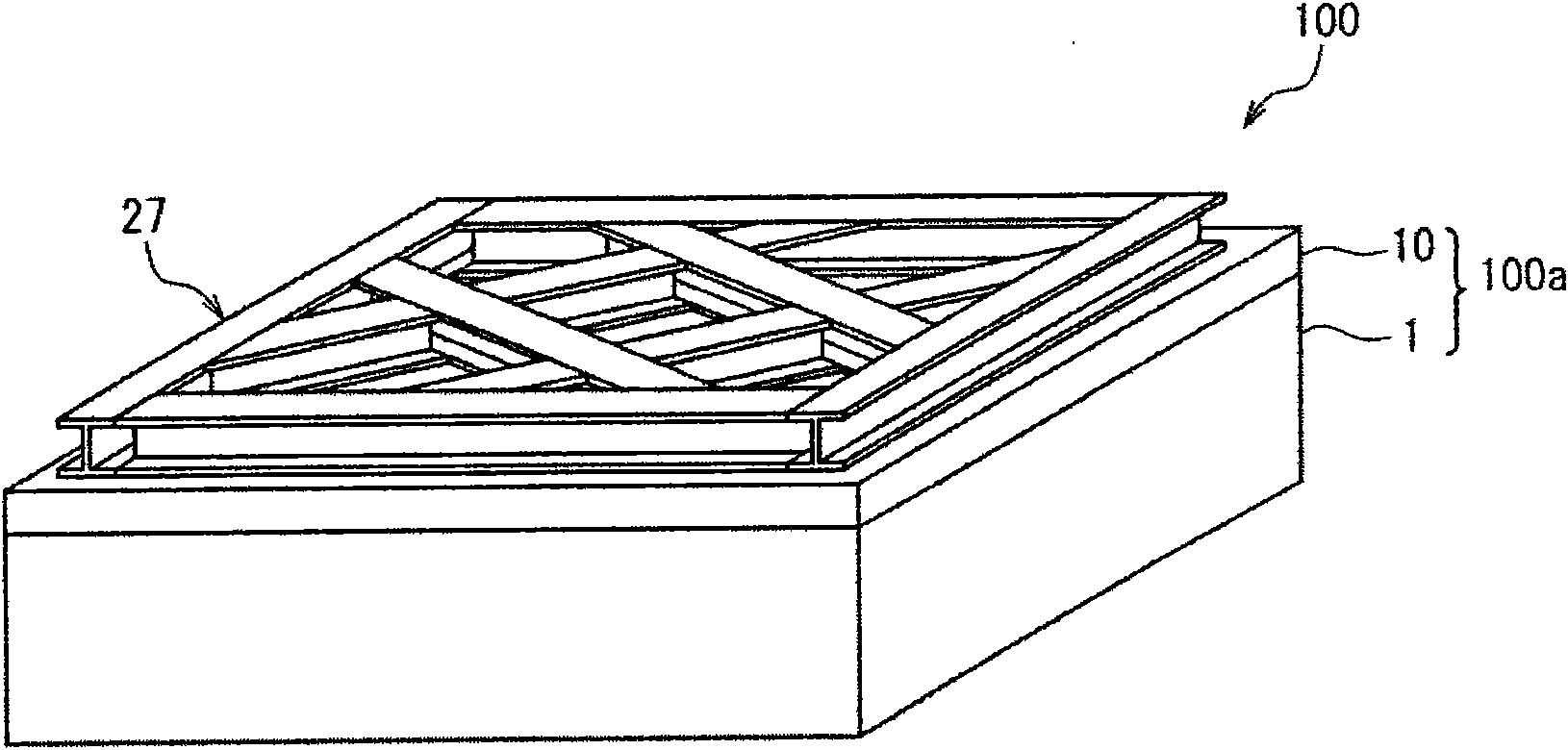
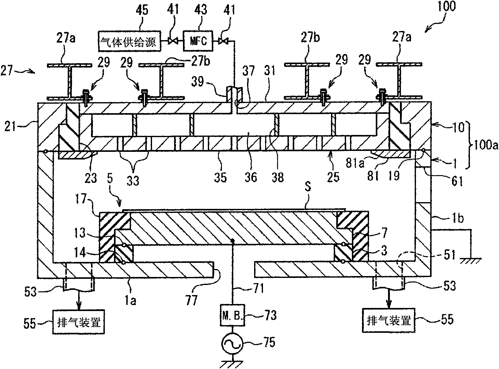
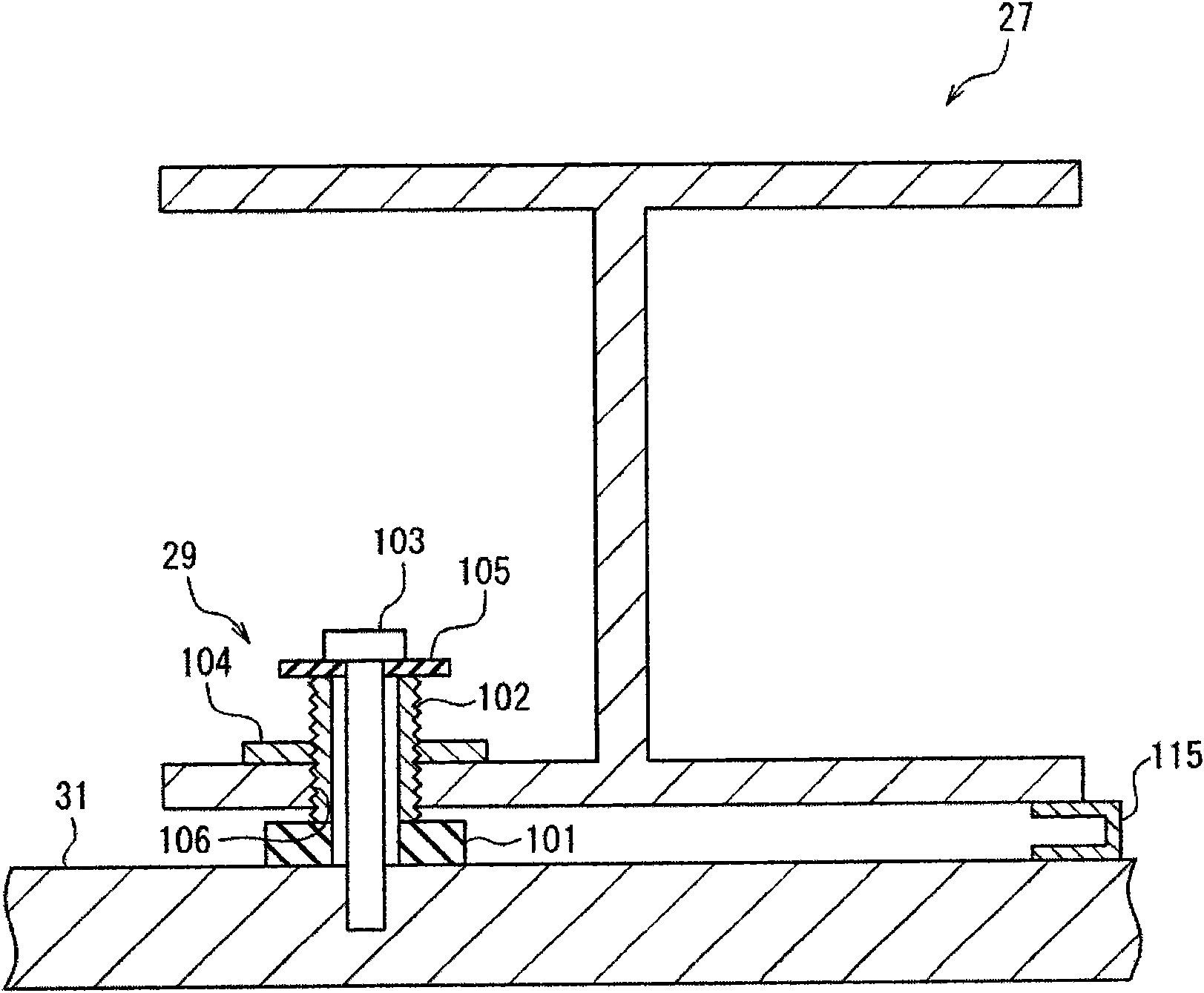
[0061] Hereinafter, embodiments of the present invention will be described in detail with reference to the drawings. First, refer to Figure 1 to Figure 5 , the plasma etching apparatus 100 having the vacuum container of this embodiment will be described. figure 1 is a perspective view showing the appearance of the plasma etching apparatus 100, figure 2 is a cross-sectional view showing a schematic configuration of the plasma etching apparatus 100 . in addition, image 3 and Figure 4 is to zoom in figure 2 The cross-sectional view of the main part. The plasma etching apparatus 100 is configured as an apparatus for performing a plasma etching process on, for example, a glass substrate (hereinafter simply referred to as “substrate”) S for FPD. In addition, examples of the FPD include a liquid crystal display (LCD), a photoluminescence (ElectroLuminescence: EL) display, a plasma display (PDP), and the like.
[0062] Such as figure 1 and figure 2 As shown, the plasma ...
no. 2 approach
[0089] Next, refer to Figure 6 and Figure 7 A second embodiment of the present invention will be described. Figure 6 is the same as figure 2 A cross-sectional view of a main part of a plasma etching apparatus having substantially the same configuration as the plasma etching apparatus 100 of the first embodiment shown. Hereinafter, with the first embodiment ( Figure 1 to Figure 5 ) will be described focusing on the differences, and the same reference numerals will be used for the same structures, and their descriptions will be omitted. In addition, since the overall structure of the plasma etching apparatus of this embodiment can be grasped by referring to the plasma etching apparatus 100 of 1st Embodiment, illustration is abbreviate|omitted.
[0090] This plasma etching apparatus differs from the plasma etching apparatus 100 of the first embodiment in that a conductive plate 111 and a support plate 113 are provided between the bottom plate 31 of the shower head 25 ser...
no. 3 approach
[0101] Next, refer to Figure 8 A third embodiment of the present invention will be described. Hereinafter, with the first embodiment ( Figure 1 to Figure 5 ) will be described focusing on the differences, and the same drawings will be used for the same configuration, and the description will be omitted. Figure 8 It is a perspective view showing the external configuration of the plasma etching apparatus 200 according to the third embodiment of the present invention. The plasma etching apparatus 200 has a rectangular cylindrical lower container 1 made of, for example, aluminum whose inner surface is oxidized (anodized), and an upper container 210 which is openably and closably combined with the lower container 1 . A plasma processing container 200 a serving as a vacuum container is constituted by the lower container 1 and the upper container 210 .
[0102] The upper container 210 of the plasma processing container 200 a has a frame body 21 , an unillustrated shower head (u...
PUM
 Abstract
Description
Claims
Application Information
 - R&D
- Intellectual Property
- Life Sciences
- Materials
- Tech Scout
- Unparalleled Data Quality
- Higher Quality Content
- 60% Fewer Hallucinations
Browse by: Latest US Patents, China's latest patents, Technical Efficacy Thesaurus, Application Domain, Technology Topic, Popular Technical Reports.
© 2025 PatSnap. All rights reserved.Legal|Privacy policy|Modern Slavery Act Transparency Statement|Sitemap|About US| Contact US: help@patsnap.com