
Multi-chamber type steel tube concrete special-shaped column

A technology of steel tube concrete and special-shaped columns, which is applied in the direction of columns, pier columns, pillars, etc., can solve the problems of increasing the difficulty of construction and design of special-shaped columns, reducing the overall performance of components, and prone to premature buckling, so as to achieve better cross-section performance and benefit The effect that up, construction making is easy

Inactive Publication Date: 2009-10-14
BEIHANG UNIV
View PDF0 Cites 28 Cited by
  • Summary
  • Abstract
  • Description
  • Claims
  • Application Information

AI Technical Summary

Problems solved by technology

These measures make up for the defects of ordinary concrete-filled steel tube special-shaped columns to a certain extent, and suppress or slow down the local buckling of steel plates. However, the above-mentioned structural measures also increase the difficulty of construction and design of special-shaped columns, which is not easy to apply
Some researchers have proposed to weld two or three rectangular steel tubes into concrete-steel composite special-shaped columns. This kind of cross-section structure is simple and convenient for construction, but there are edges with relatively large width and thickness on the cross-section, which is prone to premature buckling and reduces the structural strength of the component. overall performance
In addition, this cross-sectional size is also restricted by steel pipe specifications, which limits its further application

Method used


Image

  • Multi-chamber type steel tube concrete special-shaped column
  • Multi-chamber type steel tube concrete special-shaped column
  • Multi-chamber type steel tube concrete special-shaped column

Examples


Embodiment Construction

[0023] The present invention will be further described in detail below in conjunction with the accompanying drawings.

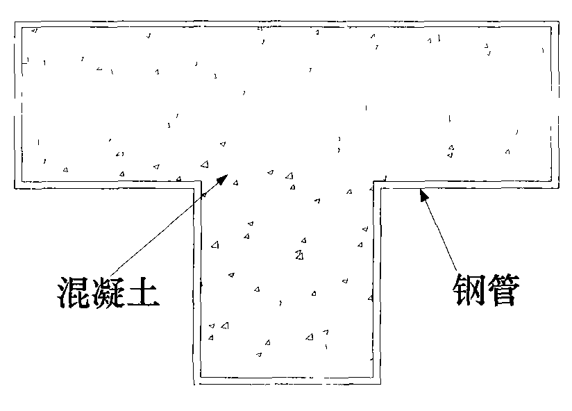
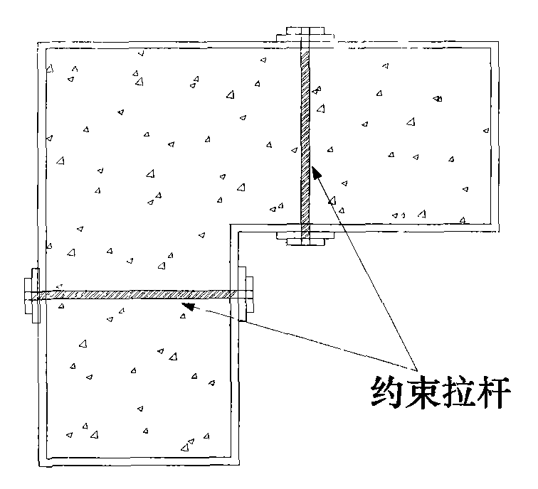
[0024] The invention is a multi-chamber concrete-filled special-shaped column, which is composed of U-shaped steel 1, rectangular steel pipe 2 and concrete 3 poured into it. The U-shaped steel 1 and rectangular steel pipe 2 are welded together to form a special-shaped column with different sections. Column, the entire special-shaped column section is divided into multiple chambers by U-shaped steel 1 and rectangular steel pipe 2, and concrete 3 is filled into U-shaped steel 1 and rectangular steel pipe 2.

[0025] Such as Figure 5a As shown, the U-shaped steel 1 is bent or welded by steel plates, such as Figure 5b As shown, the rectangular steel pipe 2 is formed by bending a steel plate and then welding it or directly welding a steel plate.

[0026] The special-shaped column mentioned in the present invention refers to that the cross-sectional form of the...


PUM


Abstract

The invention discloses a multi-chamber type steel tube concrete special-shaped column, consisting of U-shaped steel, a rectangular steel tube and concrete cast in the tube. The U-shaped steel is mutually welded with the rectangular steel tube to form special-shaped columns with different sections. The whole section is divided into a plurality of chambers by the U-shaped steel and the rectangular steel tube, and the concrete is filled in the chambers. The U-shaped steel is formed by bending or welding a steel plate and the rectangular steel tube is formed by directly welding or first blending and then welding the steel plate. By dividing the section into a plurality of chambers, the special-shaped column can enhance the interaction between the steel and concrete, reduces the ratio of width to thickness of the steel plate and is beneficial to give full play of material performance and the improvement of section performance; and the directly stressed U-shaped steel and the directly stressed rectangular steel tube decrease the dimension of sections, eliminate the negative angle of 90 degrees, boost the bearing capacity of the special-shaped column and improve anti-seismic performance. The special-shaped column is simple in manufacture, guarantees the quality of concrete vibrating and casting, is convenient for construction and manufacture and has comparatively good economic benefits.

Description

technical field [0001] The invention belongs to the field of construction engineering, and in particular relates to a multi-chamber special-shaped steel pipe concrete column. Background technique [0002] With the continuous increase of my country's steel output, the continuous development of the economy, and the continuous demand for green and environmentally friendly buildings, steel structure houses have developed rapidly in our country. Considering our country's large population and relatively insufficient land resources, it is advisable to develop multi-storey and small high-rise steel structure residences. Most of these steel structure houses adopt frame-support system or frame-concrete shear wall (core tube) system. The columns can be steel columns, steel pipe concrete columns and steel-reinforced concrete columns, and the latter two are composite columns. In small high-rise buildings, composite columns are less steel than steel columns, which can reduce the project ...

Claims


Application Information

Patent Timeline
IPC IPC(8): E04C3/34
Inventor 屠永清刘林林叶英华
Owner BEIHANG UNIV
Learn More