
Method for electrolytically etching pictures and text on metal plate and device thereof

An electrolytic etching, metal plate technology, applied in the direction of electrolysis process, electrolysis components, etc., can solve the problems of waste, unfavorable etching interface update, unfavorable circuit board walking, etc.

Active Publication Date: 2009-09-30
常州正成机电科技有限公司
View PDF1 Cites 9 Cited by
  • Summary
  • Abstract
  • Description
  • Claims
  • Application Information

AI Technical Summary

Problems solved by technology

This invention has the following disadvantages: due to the face-to-face arrangement of the positive electrode and the negative electrode, there is a gap between the etched two adjacent circuit boards during continuous etching, and the electrolyte passes through the gap to cause a short circuit between the positive electrode and the negative electrode. Causes waste of power; the electrolyte is sprayed vertically to the surface of the circuit board, which is not conducive to the walking of the circuit board, and is also not conducive to the renewal of the etching interface, which affects the etching efficiency; there is a large distance between the positive electrode, the negative electrode and the circuit board, and more Electrolyte, causing waste

Method used


Image

  • Method for electrolytically etching pictures and text on metal plate and device thereof
  • Method for electrolytically etching pictures and text on metal plate and device thereof
  • Method for electrolytically etching pictures and text on metal plate and device thereof

Examples


Embodiment Construction

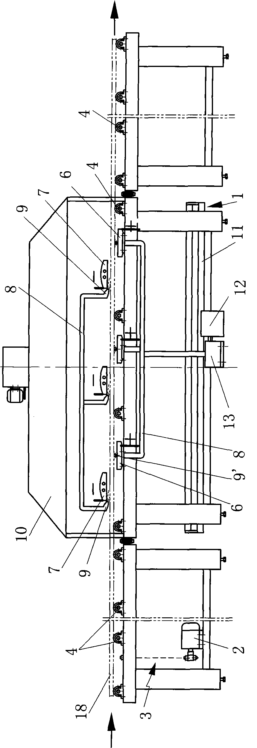
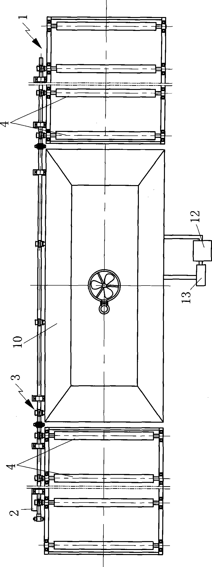
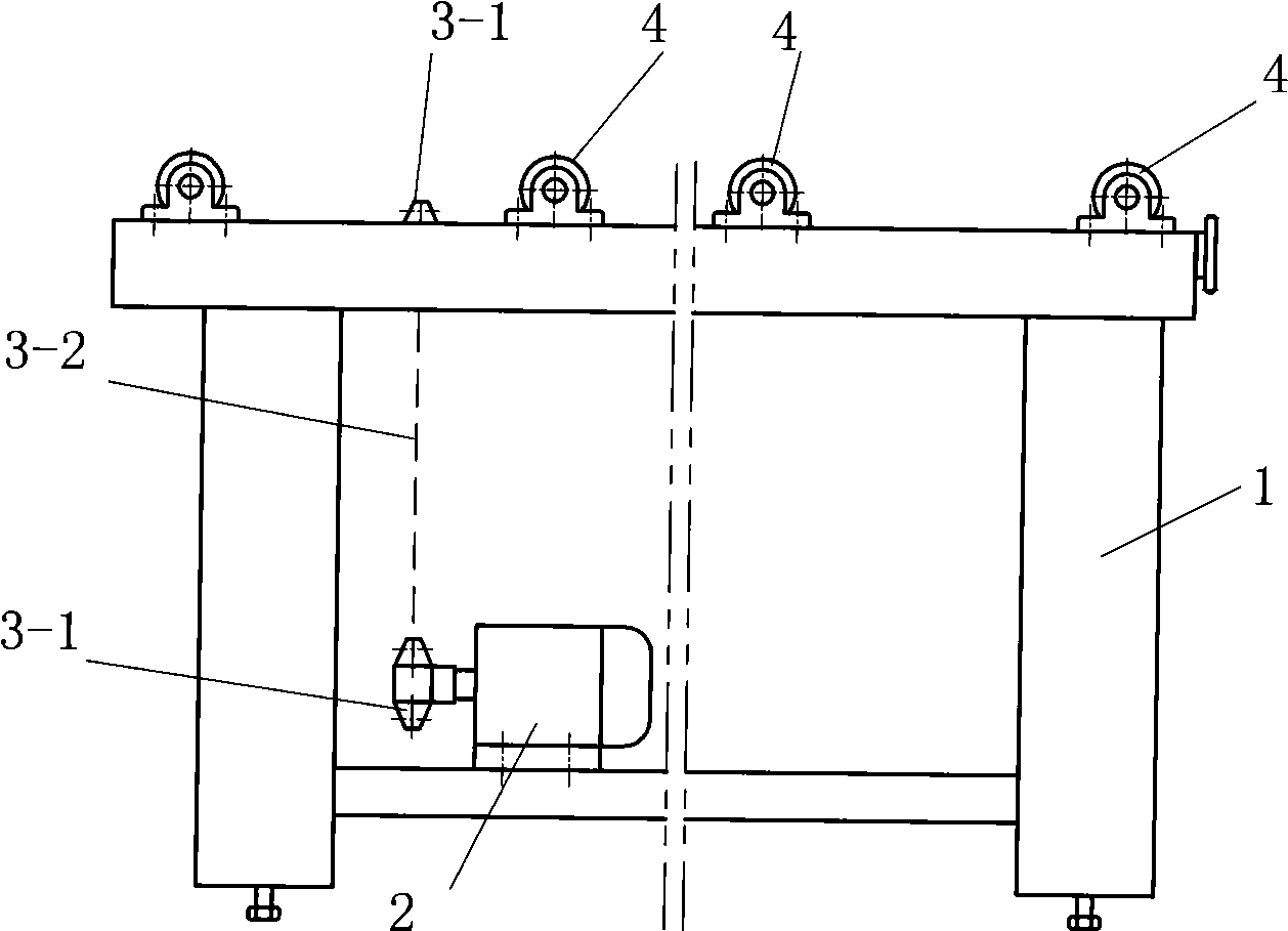
[0026] Such as figure 1 , 2 , 5, and 7, the method for electrolytically etching a metal plate of the present invention includes a method for electrolytically etching a metal plate, including step a. Plate 18 is placed on conveying roller 4 or conveyer belt, b, metal plate 18 is moved to electrolysis zone by conveying roller 4 or conveyer belt, negative electrode 7 of c, electrolysis zone is on, positive electrode 6 is below, and vertical The direction is dislocated, and the metal plate 18 is moved so that the upper surface of the metal plate 18 faces the negative electrode 7 and maintains a certain gap with the negative electrode 7; the lower surface of the metal plate 18 faces the positive electrode 6 and has a gap with the positive electrode 6 Keep a certain gap; d, spray electrolyte solution in the gap between the upper surface of the metal plate 18 and the negative electrode 7 along the moving direction of the metal plate 18; e, simultaneously move toward the gap between ...


PUM


Abstract

The invention discloses a method for electrolytically etching pictures and text on a metal plate and a device thereof. The method comprises the following steps: putting a metal plate with an electrolytically etched picture and text layer on the upper surface on a conveyer roller and moving to an electrolytic region with an upper negative electrode and a lower positive electrode which are arranged to be staggered in the vertical direction; simultaneously jetting electrolyte in a gap between the upper surface of the metal plate and the negative electrode along the moving direction of the metal plate and a gap between the lower surface of the metal plate and the positive electrode; and applying voltages on the positive electrode and the negative electrode so that the electrolytic etching region on the upper surface of the metal plate is electrolytically etched. The device comprises a stand, a motor, a transmission device, the conveyer roller, the positive electrode, the negative electrode, an electrolyte pipeline, an upper nozzle and a lower nozzle. The invention hardly generates short circuits and has high etching efficiency, high radiation speed and reasonable structure.

Description

technical field [0001] The invention relates to a method and a device for performing electrolytic etching on a metal plate on a passing conveying device. Background technique [0002] The existing continuous electrolytic etching method for metal materials is mainly used for metal coils or strips, and the electrolytic etching of metal plates can usually only be performed alone, so the production efficiency of electrolytic etching of metal plates is low. The Chinese invention patent application number is 200680006806.5, which discloses a device and method for etching substrates. The invention sprays electrolytic (etching) liquid onto the circuit board in the form of a spray or similar forms. The spraying device is in contact with one pole of the power supply, and the circuit board Contact with the other pole of the power source to speed up the etching process. This invention has the following disadvantages: due to the face-to-face arrangement of the positive electrode and the...

Claims


Application Information

Patent Timeline
Patent Type & Authority Applications(China)
IPC IPC(8): C25F3/02C25F7/00
Inventor 周丁政
Owner 常州正成机电科技有限公司
Learn More