Polymer electrolyte fuel cell
A polymer electrolyte and fuel cell technology, applied in solid electrolyte fuel cells, fuel cells, fuel cell grouping, etc., can solve problems such as uneven contact pressure
- Summary
- Abstract
- Description
- Claims
- Application Information
AI Technical Summary
Problems solved by technology
Method used
Image
Examples
no. 1 approach
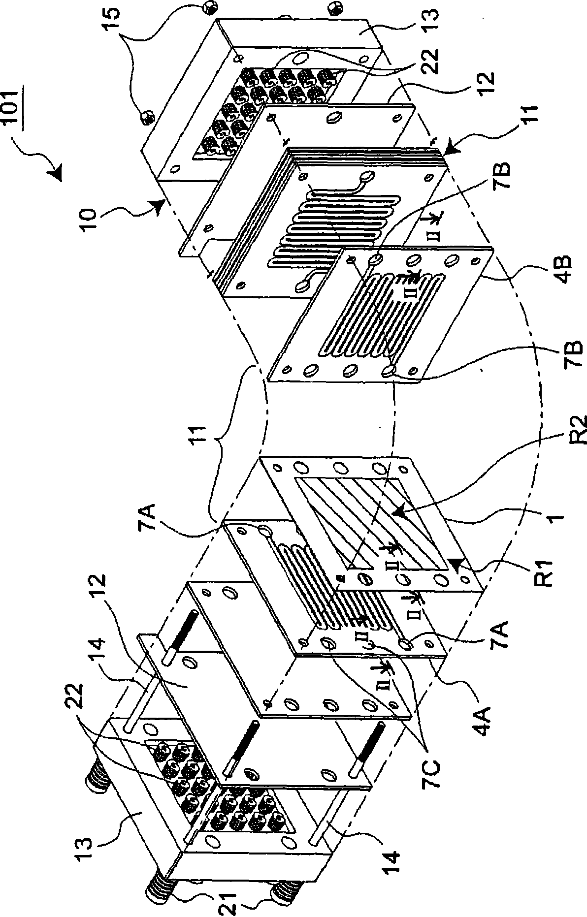
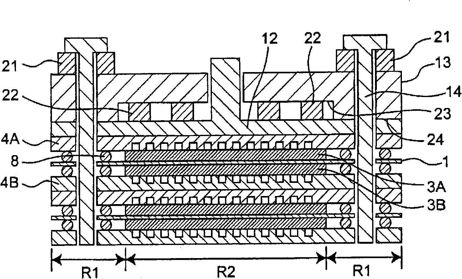
[0071] A schematic perspective view showing the structure of a fuel cell 101, which is an example of a polymer electrolyte fuel cell (PEFC) according to an embodiment of the present invention, in a partially disassembled state is shown in figure 1 middle. Such as figure 1 As shown, the fuel cell 101 is formed by stacking a plurality of unit cell modules. Additionally, the figure 1 A partial schematic cross-sectional view (cross-sectional view along line II-II) of the peripheral portion of the unit cell module in the fuel cell 101 is shown in figure 2 middle.
[0072] Such as figure 1 As shown, the fuel cell 101 is configured as follows: in a state where a plurality of unit cell modules 11 serving as a unit structure of a power generating device in the fuel cell are stacked, a pair of collector plates 12 and end plates are arranged at both ends. 13 and sandwich it, and fasten it with fastening screws 14 and nuts 15 (an example of fastening members) penetrating the screw h...
Embodiment 1
[0101] Here, will figure 1 The fastening structure of the above-mentioned embodiment is used as Example 1, and the arrangement relationship of the outer spring 21 and the inner spring 22 in the end plate 13 is shown in Figure 4A middle. Such as Figure 4A Shown, in the fastening structure of embodiment 1, such as figure 1 and Figure 3A As shown, 25 inner springs 22 are arranged in the recess 23 between the end plate 13 and the collector plate 12 . As the inner spring 22, a spring having a spring constant of 7 kgf / mm was used, and a load of 840 kgf was generated by shrinking 4.8 mm from the free length. In addition, at the four corners of the outer surface of the end plate 13, as the outer spring 21, a spring with a spring constant of 50 kgf / mm is used, and it is compressed by 5 mm from the free length with four fastening screws 14 to generate a spring of 1000 kgf. Load, tighten with nut 15.
[0102] In addition, in order to confirm the pressure distribution in the elec...
Embodiment 2
[0106] Next, a schematic diagram of the arrangement structure of the outer spring 21 and the inner spring 22 in the fastening structure of Embodiment 2 of the present invention is shown in Figure 6A middle.
[0107] Such as Figure 6A As shown, in Example 2, instead of disposing the outer springs 21 at the corners of the end plate 13 , four outer springs 21 are disposed near the midpoint positions of the edges of the rectangular end plate 13 . In addition, the respective inner springs 22 are not evenly arranged in the electrode arrangement region R2, but are arranged such that their centers are located in the electrode arrangement region R2 inside the quadrilateral formed by the line segments L1 connecting the four outer springs 21. The inner spring 22 is arranged. Furthermore, a plurality of inner springs 22 are arranged on a diagonal line L2 of a quadrilateral formed by line segments L1 connecting the four outer springs 21 . First, one inner spring 22 is arranged at the ...
PUM
| Property | Measurement | Unit |
|---|---|---|
| thickness | aaaaa | aaaaa |
| current density | aaaaa | aaaaa |
Abstract
Description
Claims
Application Information
 - R&D
- Intellectual Property
- Life Sciences
- Materials
- Tech Scout
- Unparalleled Data Quality
- Higher Quality Content
- 60% Fewer Hallucinations
Browse by: Latest US Patents, China's latest patents, Technical Efficacy Thesaurus, Application Domain, Technology Topic, Popular Technical Reports.
© 2025 PatSnap. All rights reserved.Legal|Privacy policy|Modern Slavery Act Transparency Statement|Sitemap|About US| Contact US: help@patsnap.com


