
U-shaped heating element of silicon tetrachloride hydrogenation furnace and manufacturing process thereof

A silicon tetrachloride, manufacturing process technology, applied in the direction of furnace heating element, metal material coating process, gaseous chemical plating, etc., can solve the problem of short service life, unsatisfactory use reliability, corrosion resistance of heating element and Erosion performance is not high, to achieve the effect of high carbon fiber content, prevent erosion and surface peeling

Inactive Publication Date: 2009-09-23
HUNAN NANFANG BOYUN NOVEL MATERIAL
View PDF0 Cites 14 Cited by
  • Summary
  • Abstract
  • Description
  • Claims
  • Application Information

AI Technical Summary

Problems solved by technology

Because the heating element always works in the environment of high temperature and corrosive atmosphere, and the corrosion resistance and erosion performance of the existing heating element are not high, so its service life is short and the reliability of use is not satisfactory

Method used


Image

  • U-shaped heating element of silicon tetrachloride hydrogenation furnace and manufacturing process thereof

Examples


Embodiment 1

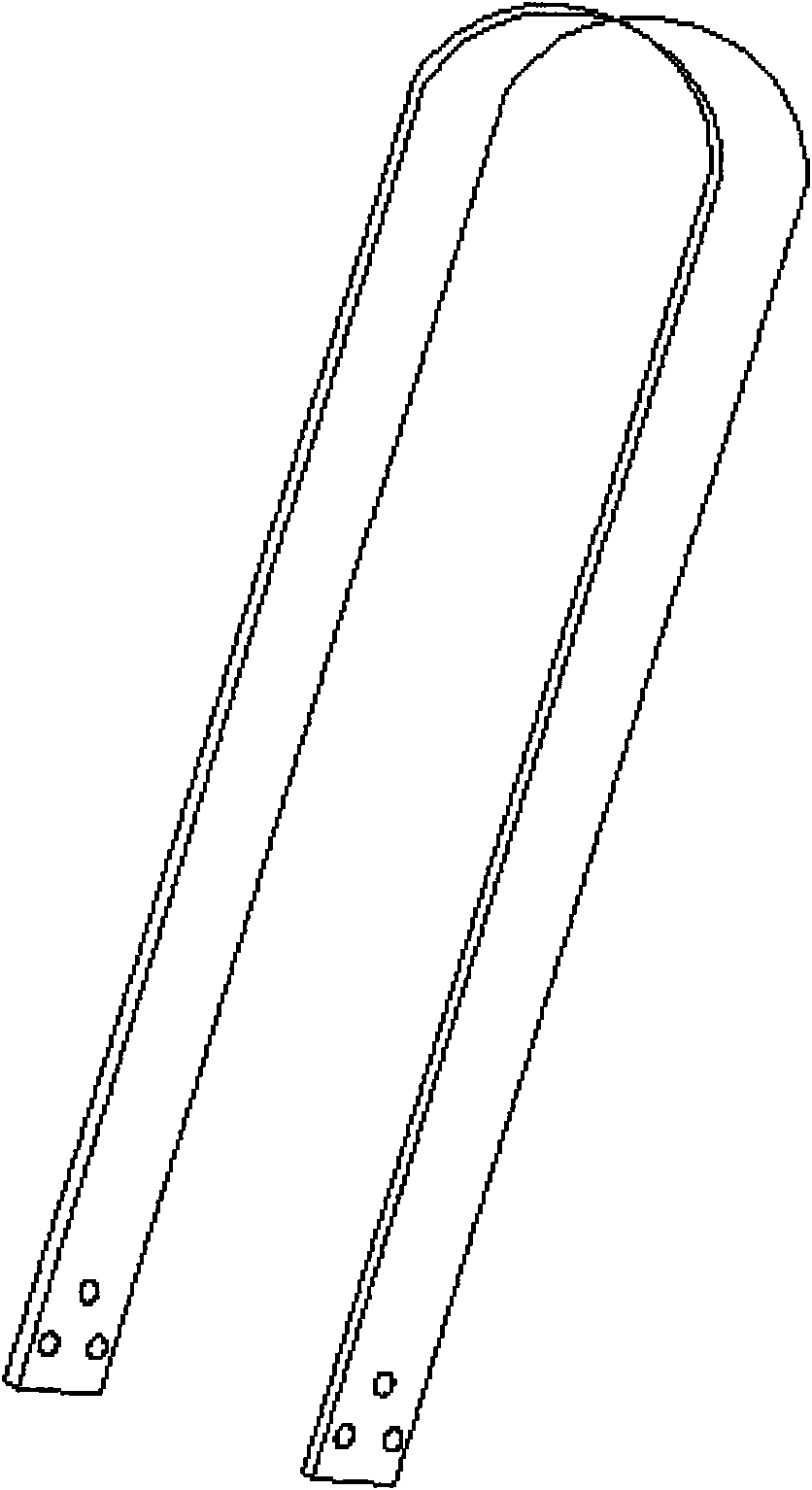
[0020] shaped like figure 1 As shown, the total length of the unfolded body is 3.6 meters, the width is 80 mm, and the thickness of the finished product is 8 mm; the green body is composed of two-dimensional polyacrylonitrile carbon fiber fabric laminates, and its weight is 50% of the total weight of the green body and the matrix; the matrix is ​​made of impregnated carbon Composed of chemical vapor deposition carbon, wherein the content of chemical vapor deposition carbon is 20% of the total weight of the green body and the substrate; the density of the heating element is 1.5g / cm 3 ; The thickness of the silicon carbide insulating layer on the surface is 15 μm.

[0021] The manufacturing process of the U-shaped heating element in this embodiment: (1) Laminate the green body with two-dimensional polyacrylonitrile carbon fiber fabric, lay the green body flat on the U-shaped tire mold, and place it between the tire mold and the indenter. Put in plate-like high-speed iron, and c...

Embodiment 2

[0024] The height of the U-shaped heating element is 2 meters, and the unfolded length is 4.2 meters. The green body is composed of needle-punched three-dimensional polyacrylonitrile carbon fiber felt, and its weight is 55% of the total weight of the green body and the matrix; the matrix is ​​composed of impregnated carbon and chemical vapor deposition carbon, wherein the content of chemical vapor deposition carbon is the green body and the matrix. 30% of the total weight; heating body density 1.36g / cm 3 ; Surface coating thickness is 20 μm; Remaining with embodiment 1.

[0025] The U-shaped heating element manufacturing process of this embodiment: (1) Use three-dimensional polyacrylonitrile needle-punched carbon fiber felt to make a green body, spread the green body on the U-shaped tire mold, and place Put into strips and other high-speed iron, and compress the green body to the required shape and size; the thickness of the compressed green body is 8mm, and the density is 0....


PUM

PropertyMeasurementUnit
Densityaaaaaaaaaa
Thicknessaaaaaaaaaa
Densityaaaaaaaaaa

Abstract

The invention provides a U-shaped heating element of a silicon tetrachloride hydrogenation furnace and a manufacturing process thereof. The U-shaped heating element of the silicon tetrachloride hydrogenation furnace consists of a green body, a matrix and a silicon carbide surface coating, wherein, the green body is prepared from 2D (two-dimensional) carbon fiber laminated fabric or quasi-3D (three-dimensional) carbon fiber needle felt with the weight not less than 50% of the total weight of the product; the matrix is composed of impregnated carbon and CVD-based (chemical vapor deposition) carbon, wherein, the content of the CVD-based carbon is not more than 30% of the total weight of the green body and the matrix; the material density of the heating element is higher than or equal to 1.3g / cm3; and the thickness of the silicon carbide surface coating is 10 to 100 mum. The U-shaped heating element of the silicon tetrachloride hydrogenation furnace has the advantages of high corrosion and erosion resistance, long service life and high reliability.

Description

technical field [0001] The invention relates to a U-shaped heating element of a hydrogenation furnace and a manufacturing process thereof, in particular to a U-shaped heating element of a carbon-carbon composite material silicon tetrachloride hydrogenation furnace and a manufacturing process thereof. Background technique [0002] The hydrogenation furnace is the key equipment for the recycling of chlorosilane, and it is an important guarantee for high efficiency, energy saving, environment-friendly closed-loop production and high-purity polysilicon. [0003] In 1955, Siemens successfully developed and utilized H 2 Reduced SiHCl 3 , Deposit and produce polysilicon on the silicon core heating element. Tail gas emitted from polysilicon production mainly contains SiH 4 、SiH 2 Cl 2 , hydrogen, hydrogen chloride and unreduced SiHCl 3 , these exhaust gases must be dealt with. The treatment method is mainly to use a hydrogenation furnace for hydrogenation reduction, so that t...

Claims


Application Information

Patent Timeline
IPC IPC(8): H05B3/14H05B3/62B05D7/24C23C16/26B29C70/34B29K85/00
Inventor 蒋建纯张弛张新万吕国平陈志军蒋立志
Owner HUNAN NANFANG BOYUN NOVEL MATERIAL
Learn More