Low roller driving type sander

A driving type sanding machine technology, which is applied in belt grinders, grinding/polishing equipment, grinding machines, etc., can solve the problems of large torque, plate pause, plate clamping, etc., and achieve compact equipment layout, reduce pause, The effect of taking up little space

Inactive Publication Date: 2009-09-23
吴鸣
View PDF0 Cites 0 Cited by
  • Summary
  • Abstract
  • Description
  • Claims
  • Application Information

AI Technical Summary

Problems solved by technology

When the rubberized surface wears to a certain extent, the pallet will rub against the board surface, and even clamp the board to death, causing the board to stop
Moreover, the elastic coupling used to connect adjacent reducers is easily damaged. Even if it is connected with a universal cross shaft, it will be easily twisted due to the large torque, which is not conducive to popularization.

Method used


Image

  • Low roller driving type sander
  • Low roller driving type sander

Examples


Embodiment Construction

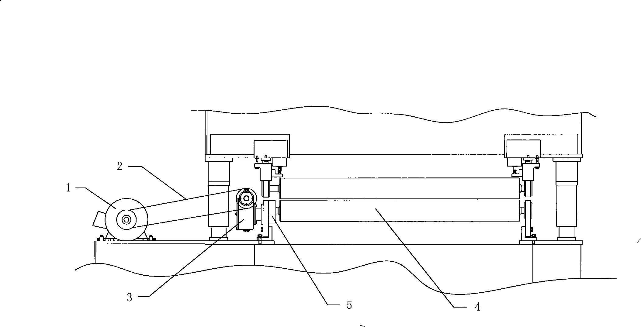
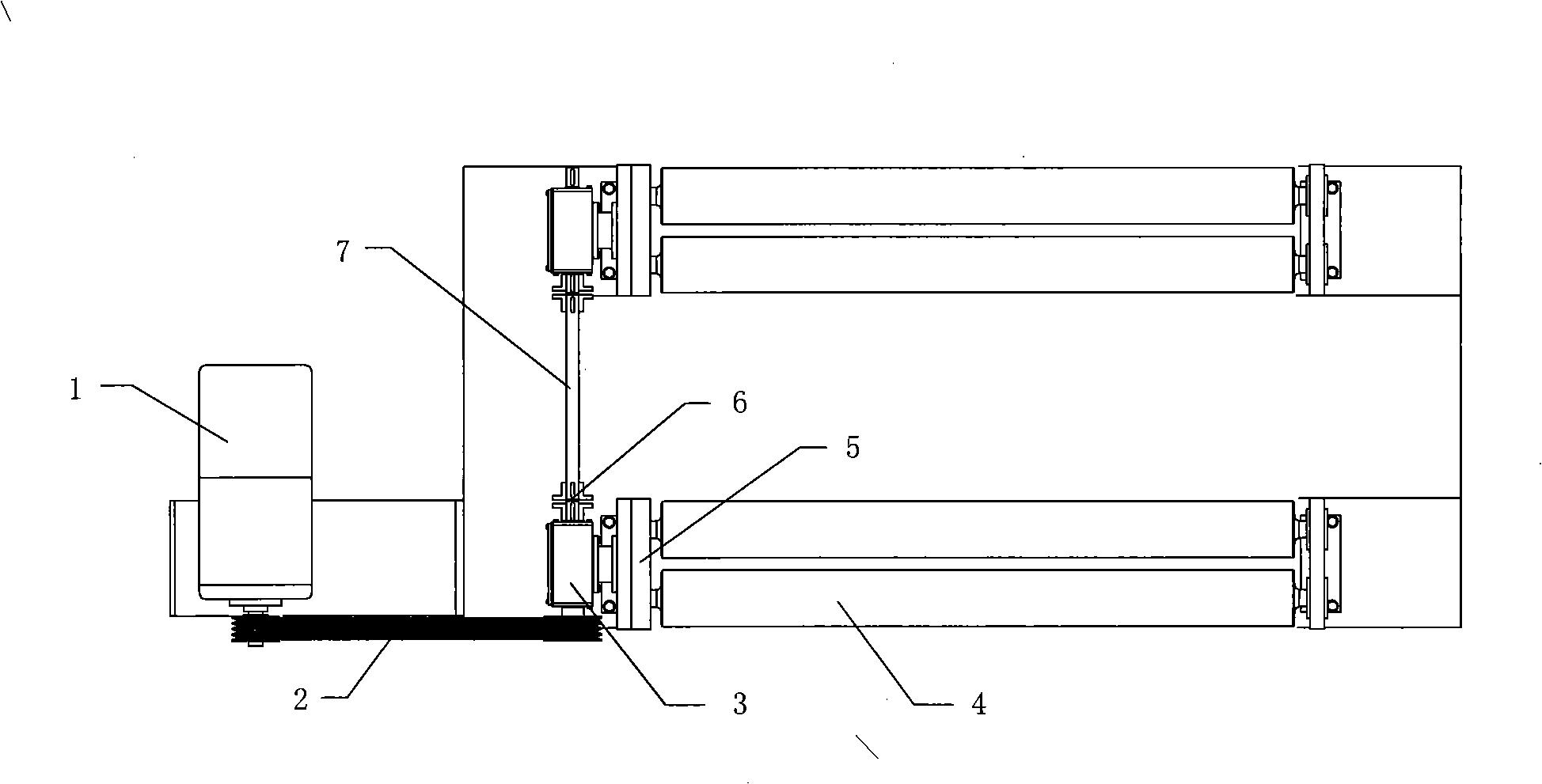
[0020] Such as figure 1 , figure 2 As shown, a lower roller driven sander includes a driving device, a transmission part, a reducer and a rubber-coated transport roller set, the drive device is connected to the reducer through a transmission part, and the rubber-coated transport roller set includes Gear box 5 and at least two rubber-covered transport rollers 4, one side of the gear box 5 is connected with the reducer, and the other side of the gear box 5 is connected with two rubber-covered transport rollers 4, the rubber-covered transport roller kit has at least two sets , the gear box 5 of each rubber-coated transport roller set is equipped with a shaft coupling, and a transmission shaft 7 is additionally installed between the shaft couplings.

[0021] According to a preferred embodiment of the present invention, the speed reducer is a worm gear speed reducer 3, which is directly connected to the intermediate gear of the rubber-covered transport roller 4, and the coupling ...


PUM


Abstract

The invention relates to a low roller driving type sander belonging to the technical field of mechanical processing equipment and comprising a driving device, a transmission part, a speed reduction machine and rubber coating transport roller external elements. The transmission part is connected between the driving device and the speed reduction machine. The low roller driving type sander is characterized in that each rubber coating transport roller external element comprises a gear box and at least two rubber coating transport rollers; one side of the gear box is connected with the speed reduction machine, and the other side of the gear box is connected with a rubber coating transport roller; at least two groups of rubber coating transport roller external elements are provided, the gear box of each rubber coating transport roller external element is provided with a coupler; and transmission shafts are additionally installed between the couplers. The invention can bear larger torque moment, has small occupied space and compact layout, largely reduces the phenomena of plate seizing and plate stopping, and prolongs the service life while reducing the failure rate.

Description

technical field [0001] The invention relates to a sander, in particular to a lower roller driven sander, which belongs to the technical field of mechanical processing equipment. Background technique [0002] At present, the widely used sanding machine in the market is to rely on the reverse rotation of the upper and lower paired rollers to drive the plate to convey the plate horizontally and straightly. The surface of the lower roller is covered with rubber or polyurethane to improve friction and has certain elasticity. Does not damage the surface of the board. Looking further, there are two forms of joint drive of the upper and lower rollers and separate drive of the lower roller, especially the single drive of the roller is more commonly used. [0003] However, the existing working space requires the reducer of the sander to be relatively small in size, which will result in a smaller input power and a correspondingly smaller output torque of the reducer. Moreover, due to...

Claims


Application Information

Patent Timeline
Patent Type & Authority Applications(China)
IPC IPC(8): B24B21/04B24B21/18
Inventor 吴鸣吴佳雯
Owner 吴鸣
Why Eureka
Try Eureka