
Multifunctional composite power cutter tower of computer numerically controlled lathe

A technology of CNC lathes and power turrets, applied in the direction of tool clamps, etc., can solve the problems of unfavorable heavy cutting, inconvenience, and the transmission mechanism 14 cannot make too large and complex changes in the structure of the gear train, etc., to achieve product structure improvement and increase torque. output effect

Inactive Publication Date: 2009-09-23
ALEX TECH MACHINERY INDAL
View PDF0 Cites 15 Cited by
  • Summary
  • Abstract
  • Description
  • Claims
  • Application Information

AI Technical Summary

Problems solved by technology

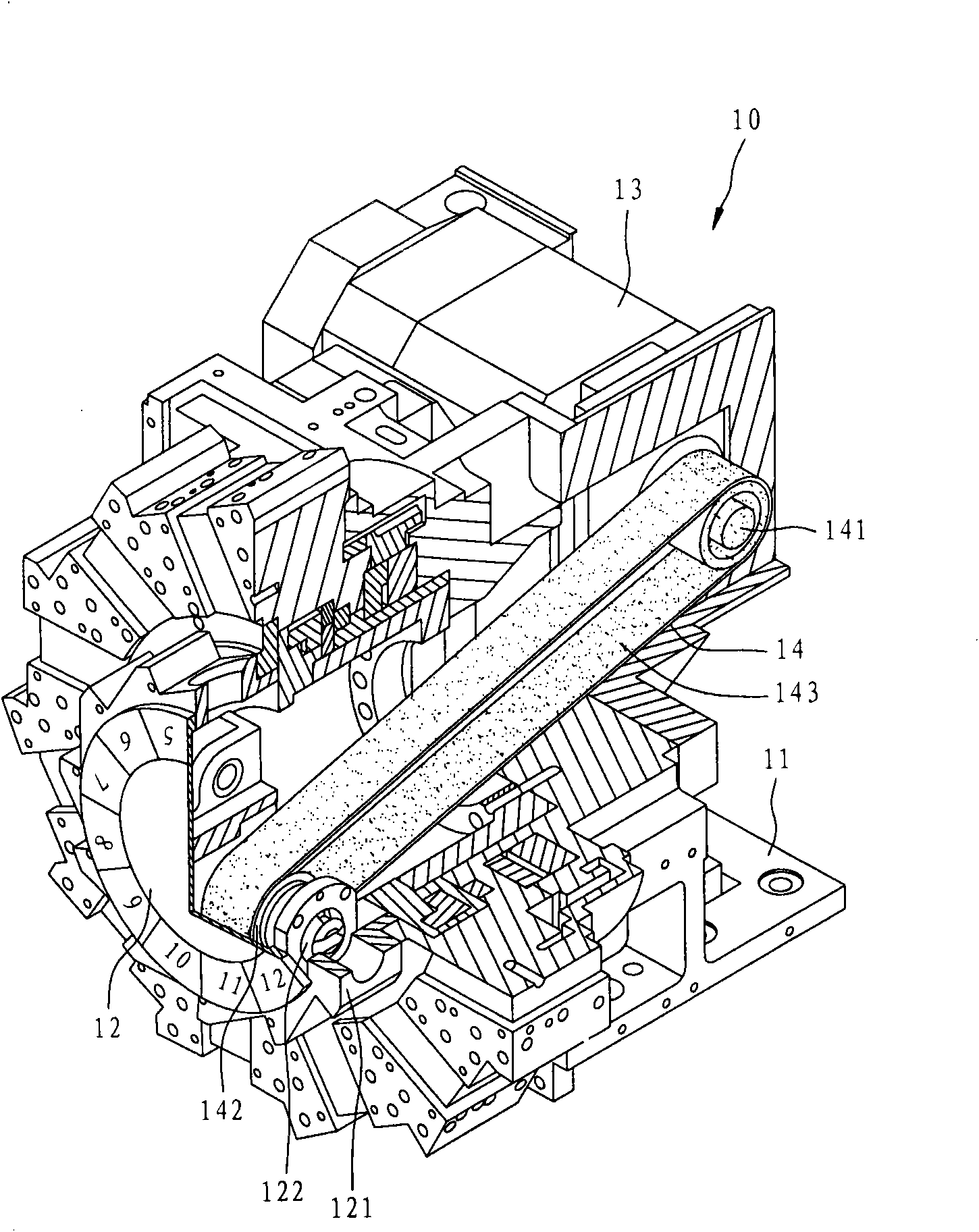
[0004] The above-mentioned turret device 10 does allow the tool itself to have the function of rotary cutting, but there is still room for improvement in use. The driving wheel 141 on the transmission mechanism 14 is arranged inside the base 11, and the driven wheel 142 is arranged on the inside of the base 11. In the central part of the cutter head 12, although there is a long-distance transmission structure formed by a belt 143 in the middle, due to the narrow and small internal space, the transmission mechanism 14 cannot make too large and complicated changes in the gear train structure, so the driving and driven wheels 141, The wheel diameter of 142 is the same, so it can only make a 1:1 constant speed ratio transmission mode, which will cause the output torque of the tool to not be effectively improved, which is not conducive to heavy cutting, and often limits the cutting operation.
[0005] This shows that the above-mentioned existing turret device obviously still has inconvenience and defects in structure and use, and needs to be further improved urgently.
In order to solve the above-mentioned problems, the relevant manufacturers have tried their best to find a solution, but for a long time no suitable design has been developed, and the general products do not have a suitable structure to solve the above-mentioned problems. Urgent problem

Method used


Image

  • Multifunctional composite power cutter tower of computer numerically controlled lathe
  • Multifunctional composite power cutter tower of computer numerically controlled lathe
  • Multifunctional composite power cutter tower of computer numerically controlled lathe

Examples


Embodiment Construction

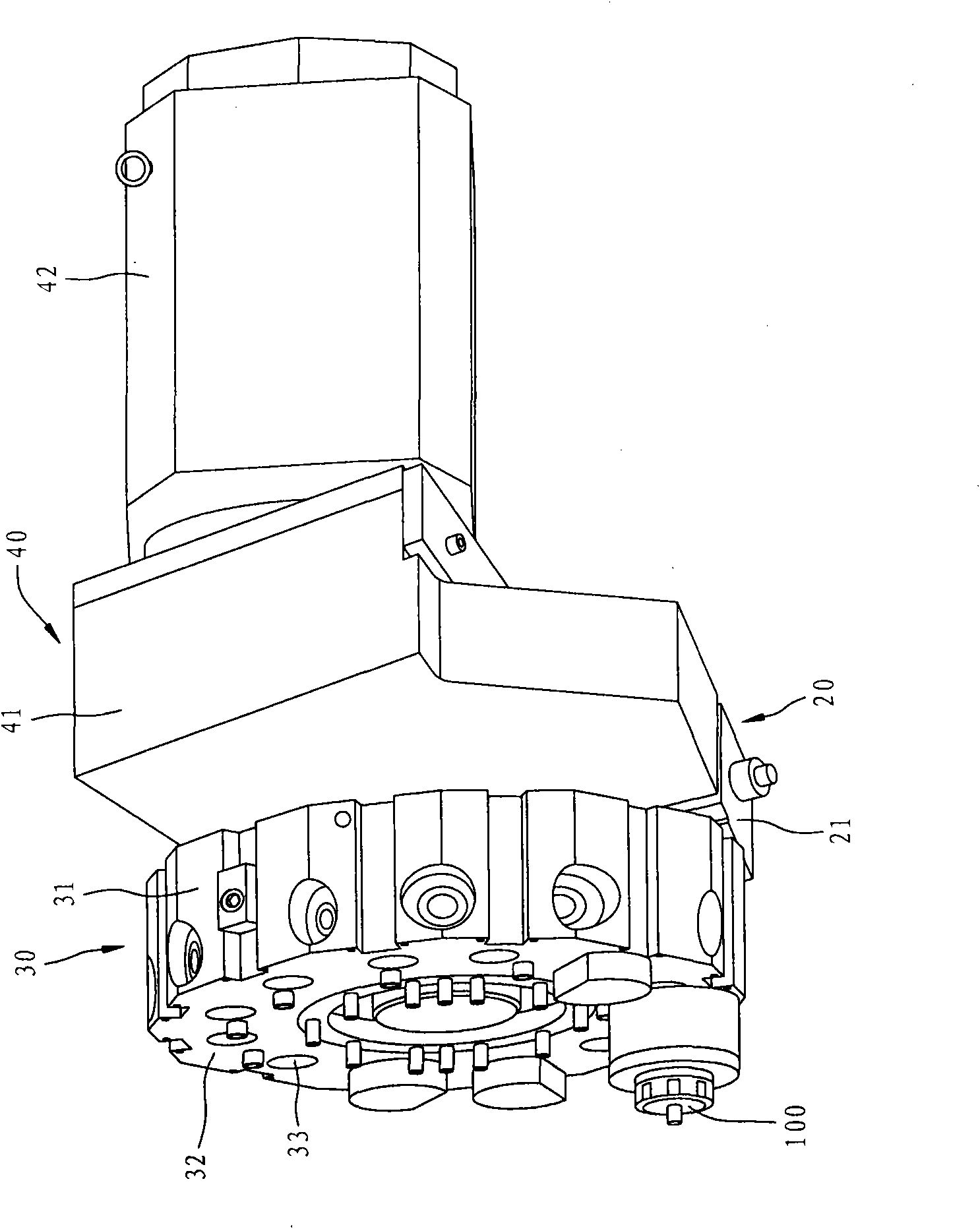
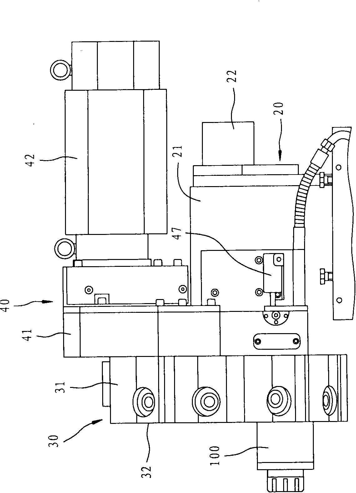
[0025] For further elaborating the technical means and effects that the present invention takes to reach the intended invention purpose, below in conjunction with accompanying drawing and two preferred embodiments, to the multi-functional composite power turret of computer numerical control lathe that proposes according to the present invention its specific Embodiments, structures, features and effects thereof are described in detail below.

[0026] The aforementioned and other technical contents, features and effects of the present invention will be clearly presented in the following detailed description of preferred embodiments with reference to the drawings. Through the description of the specific implementation mode, when the technical means and effects adopted by the present invention to achieve the predetermined purpose can be obtained a deeper and more specific understanding, but the attached drawings are only for reference and description, and are not used to explain th...


PUM


Abstract

The invention relates to a multifunctional composite power cutter tower of a computer numerically controlled lathe, which comprises a group of pedestal unit, a group of cutter head unit and a group of power transmission unit; the cutter head unit is provided with a cutter with rotary cutting function; the power transmission unit is provided with a shell seat arranged outside the pedestal unit, a motor arranged on the shell seat, a driving wheel arranged inside the shell seat to rotate by the driving of the motor, and a driven wheel arranged inside the shell seat to transmit by the driving of the driving wheel at predetermined reduction ratio; and the driven wheel finally drives the cutter to work so that the cutter can cut with large torque output. In the multifunctional composite power cutter tower, the outside of the pedestal unit is provided with the shell seat, and the driving wheel and the driven wheel are provided to achieve the speed reduction effect by a complex wheel train, so the cutter obtains high torque power output to successfully carry out various rotary cutting operations.

Description

technical field [0001] The invention relates to a computer numerical control lathe, in particular to a multifunctional composite power turret of a computer numerical control lathe which utilizes an external power transmission method to achieve high torsion output effect. Background technique [0002] The operation mode of a general computer numerical control lathe is mainly to use a group of turret devices to install various tools, let the spindle head of the lathe hold and fix a workpiece and rotate it at high speed, so that the tool can perform various turning actions on the workpiece. At present, the operation mode of computer numerical control lathe is developing towards diversification, so a turret device with the function of turning and milling combined cutting has been developed, mainly to allow the tool itself to perform rotary cutting, so that the workpiece can be further processed To achieve the function of drilling and milling. [0003] See figure 1 Shown is a t...

Claims


Application Information

Patent Timeline
IPC IPC(8): B23B29/24B23B29/32
Inventor 蔡德修
Owner ALEX TECH MACHINERY INDAL
Learn More