
Drill

A technology of drill bit and main body, which is applied in the direction of drill repairing, twist drill, drilling tool accessories, etc. It can solve the problems of messy cleaning, chip scattering, etc., and achieve the effects of reducing processing costs, ensuring tool rigidity, and preventing environmental pollution

Active Publication Date: 2009-09-09
OSG
View PDF0 Cites 12 Cited by
  • Summary
  • Abstract
  • Description
  • Claims
  • Application Information

AI Technical Summary

Problems solved by technology

In addition, when using the drill disclosed in Patent Document 1, since chips are removed only by the torque of the drill body, the discharged chips are scattered on the workpiece, making cleaning complicated.

Method used


Image

  • Drill
  • Drill
  • Drill

Examples


Embodiment Construction

[0034]

Preferred embodiments of the present invention will be described below with reference to the accompanying drawings. First, a drill 1 according to an embodiment of the present invention will be described with reference to FIG. 1 . Fig. 1 (a) is the front view of drill bit 1; Fig. 1 (b) is the side view of the drill bit seen from the arrow Ib direction of Fig. 1 (a).

[0035]

As shown in Figure 1, the drill bit 1 is a tool for drilling a workpiece (not shown) under the torque transmitted by the processing equipment (not shown), and it is integrally composed of superhard alloy, wherein the superhard alloy It is obtained by pressing sintered cemented carbide (WC) or the like, and the drill bit 1 is mainly provided with a main body 2 and a blade 3 integrally connected with the main body 2 . However, the drill 1 is not limited to cemented carbide, and may be made of high-speed tool steel.

[0036]

The main body part 2 is through the drill sleeve 10 (refer to image 3...


PUM

PropertyMeasurementUnit
diameteraaaaaaaaaa
diameteraaaaaaaaaa
lengthaaaaaaaaaa

Abstract

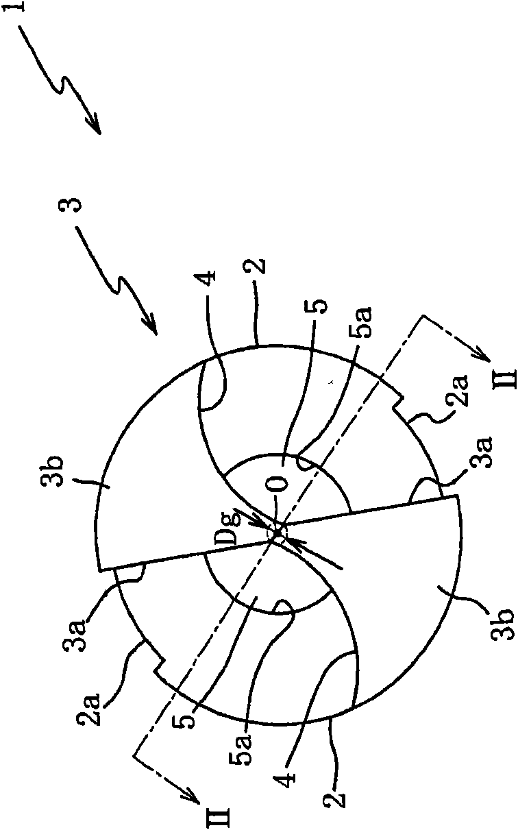
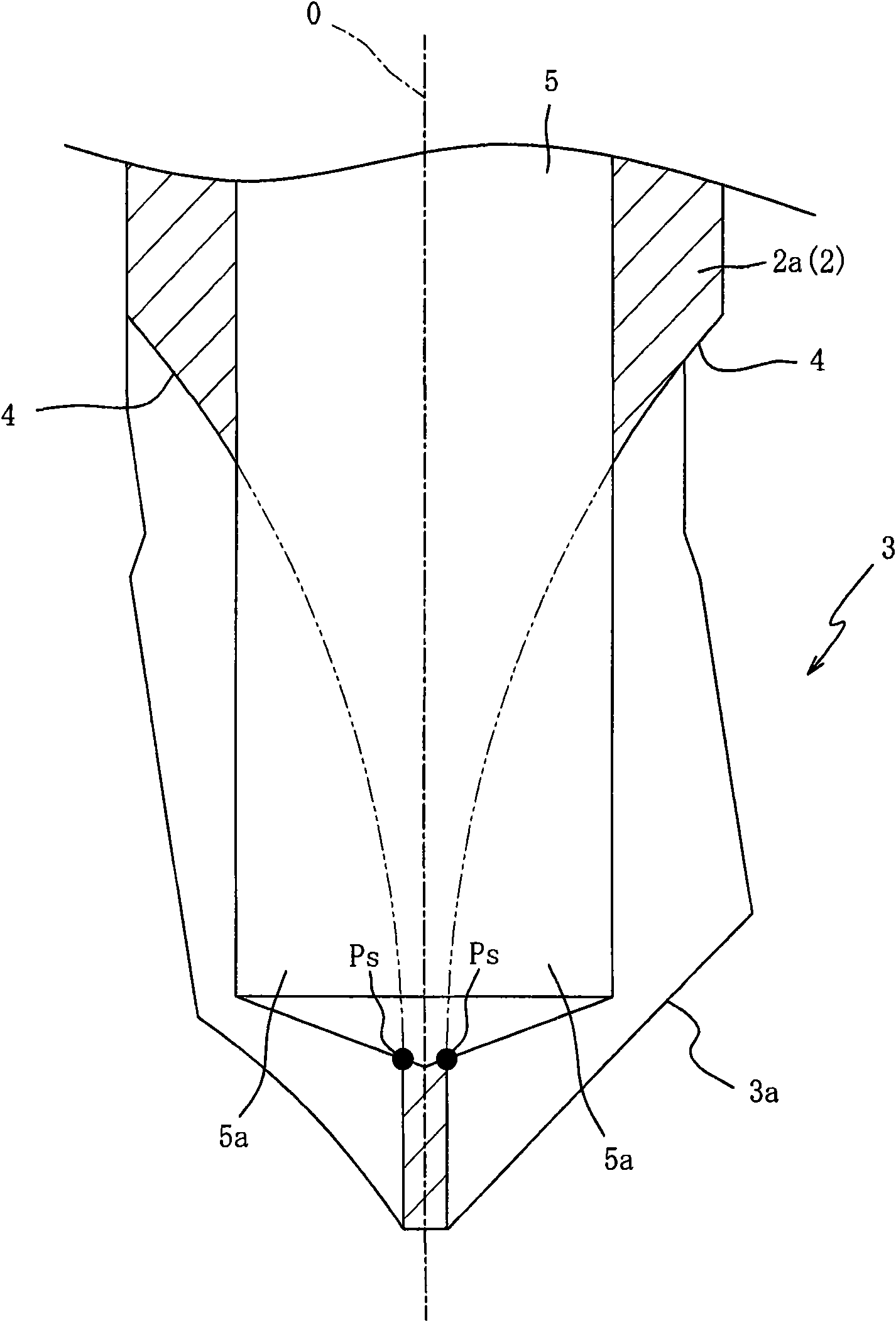
The present invention provides a drill that by forcibly suctioning and discharging of chips, attaining not only prevention of environmental pollution but also simplification of cleaning operation. Drill (1) has air suction hole (5) provided with aperture (5a). Accordingly, by air suctioning through the air suction hole (5), any chips generated at cutting processing can be forcibly suctioned from the aperture (5a). Thus, as the chips can be discharged without the use of cutting liquid, there can be attained prevention of environmental pollution. Further, as not only can the chips be forcibly suctioned from the aperture (5a) but also the chips having been suctioned from the aperture (5a) can be discharged through the air suction hole (5), scattering of the chips on the workpiece can be avoided to thereby attain simplification of cleaning operation.

Description

technical field [0001] The present invention relates to a drill bit, in particular to a drill bit which discharges chips by forced suction to prevent environmental pollution and facilitate cleaning. Background technique [0002] Usually, cutting fluid is used in the cutting process to discharge the chips generated during the cutting process. Conventionally, a drill bit known as a drill bit that uses cutting fluid to remove chips has the following structure: an oil hole and a communication hole are provided inside the main body to circulate the cutting fluid; the communication hole communicates with the oil hole and its The front end opens into the flute. [0003] With this drill, cutting fluid and chips can be discharged from the chip flute by pouring the cutting fluid flowing through the oil hole into the chip flute from the communication hole and discharging along the chip flute. [0004] In addition, there is also a drill that can remove chips without using cutt...

Claims


Application Information

Patent Timeline
Patent Type & Authority Applications(China)
IPC IPC(8): B23B51/06B23B51/00
CPCB23B2270/30B23Q11/0046B23B51/02B23B2251/14Y10T408/9097Y10T408/50B23B51/06B23B51/00
Inventor 菅野浩人大桥诚司
Owner OSG
Learn More