Eureka AIR delivers breakthrough ideas for toughest innovation challenges, trusted by R&D personnel around the world.

Hydrostatic drive with braking energy recovery feature

A kind of transmission device and hydrostatic technology, which is applied in the direction of transmission device control, power device, pneumatic power device, etc., and can solve the problem that the device cannot be converted to a driving transmission device with an open circuit

Inactive Publication Date: 2013-06-12
ROBERT BOSCH GMBH
View PDF1 Cites 0 Cited by
  • Summary
  • Abstract
  • Description
  • Claims
  • Application Information

AI Technical Summary

Problems solved by technology

[0003] A disadvantage of the transmission known from AT 395 960 B is that, on the side of the hydraulic motor, in order for the high pressure to always appear at the same connection of the hydraulic motor, the flow direction needs to be reversed
Therefore, the device proposed by AT 395 960 B cannot be transferred to a travel transmission with an open circuit

Method used


Image

  • Hydrostatic drive with braking energy recovery feature
  • Hydrostatic drive with braking energy recovery feature
  • Hydrostatic drive with braking energy recovery feature

Examples


Embodiment Construction

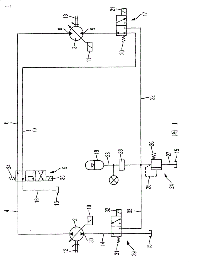
[0021] figure 1 A hydraulic circuit diagram of a first exemplary embodiment of a hydrostatic transmission according to the invention is shown. A hydrostatic transmission is a vehicle-driven traction transmission 1 by means of a hydrostatic transmission. Such a vehicle could be, for example, a wheel loader, stacker or refuse truck. Such vehicles are subject to particularly intensive drive cycles, in which acceleration and braking are repeated frequently, often one after the other. Therefore, the recovery of energy released during the braking process is of particular concern for these three types of vehicles.

[0022] The travel transmission 1 includes a hydraulic pump 2 and a hydraulic motor 3 . The hydraulic pump 2 and the hydraulic motor 3 are arranged in an open hydraulic circuit. The hydraulic pump 2 delivers pressure medium to a transfer line 4 which is connected at its transfer-side connection to the hydraulic motor 3 . The transfer line 4 is connected to a first hyd...


PUM


Abstract

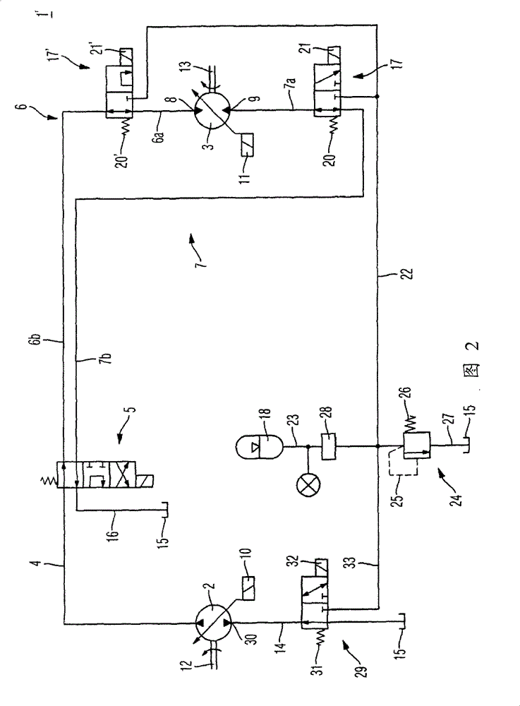
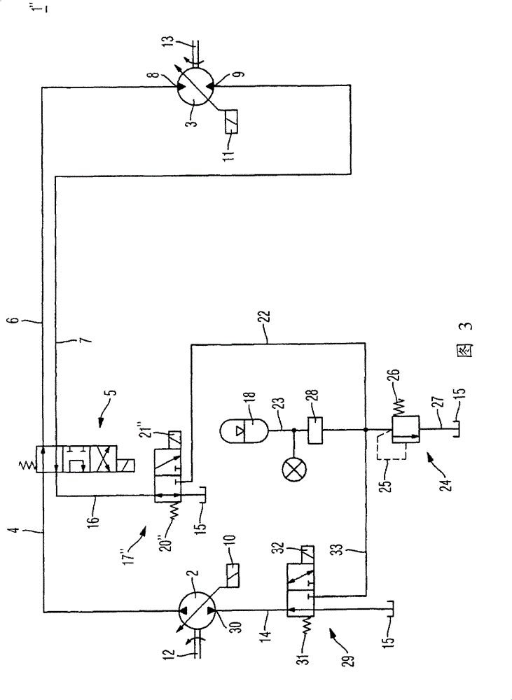
The hydrostatic drive has a hydraulic pump (2) and hydraulic motor (3) connected to each other by a feed pipe (4). The hydraulic pump and hydraulic motor are arranged in an open circuit, and a downstream connection (9) of the hydraulic motor is connected with a tank volume (15) or with the storage unit (18) by a valve device (17). A suction connection of the hydraulic pump is connected with the storage unit by another valve device.

Description

technical field [0001] The invention relates to a hydrostatic transmission with a braking energy recovery device. Background technique [0002] For the recovery of released energy in hydrostatic travel transmissions, it is known to store released kinetic energy in the form of pressure energy. For this purpose, a hydrostatic transmission in which a hydraulic pump is connected in a closed circuit to an adjustable hydraulic motor is known from AT 395 960 B. In a closed circuit, the hydraulic pump is connected to the hydraulic motor through a first working line and a second working line. The high pressure accumulator is connected to the first working line and the low pressure accumulator is connected to the second working line. Since the high-pressure accumulator is filled and then acts as a pump when recovering the released energy by the hydraulic motor, a second pressure accumulator must be provided here for equalization of the volume flow. [0003] A disadvantage of the tr...

Claims


Application Information

Patent Timeline
Patent Type & Authority Patents(China)
IPC IPC(8): B60K6/12
CPCB60K6/12F16H61/4017F16H61/4148Y02T10/6208F16H61/4096F16H61/4157Y02T10/62
Inventor 马蒂亚斯·穆勒
Owner ROBERT BOSCH GMBH
Why Eureka
Eureka Blog
Learn More