
Transonic speed controllable vortex gas dehumidifier

A transonic and gas technology, applied in the field of transonic controllable vortex gas dehumidification device, can solve the problems of large total pressure loss and low dehumidification and separation efficiency, and achieve improved back pressure efficiency, improved dehumidification and separation efficiency, and better aerodynamic performance Effect

Active Publication Date: 2009-09-02
PETROCHINA CO LTD
View PDF6 Cites 26 Cited by
  • Summary
  • Abstract
  • Description
  • Claims
  • Application Information

AI Technical Summary

Problems solved by technology

It can overcome the shortcomings of the existing supersonic gas-liquid separation technology, such as low dehumidification and separation efficiency, large total pressure loss, etc.

Method used


Image

  • Transonic speed controllable vortex gas dehumidifier
  • Transonic speed controllable vortex gas dehumidifier
  • Transonic speed controllable vortex gas dehumidifier

Examples


Embodiment Construction

[0027] Taking a transonic controllable vortex gas dehumidification device with a daily processing capacity of 400,000 standard cubic meters of natural gas as an example, the structure and working principle of the present invention will be further described in detail below.

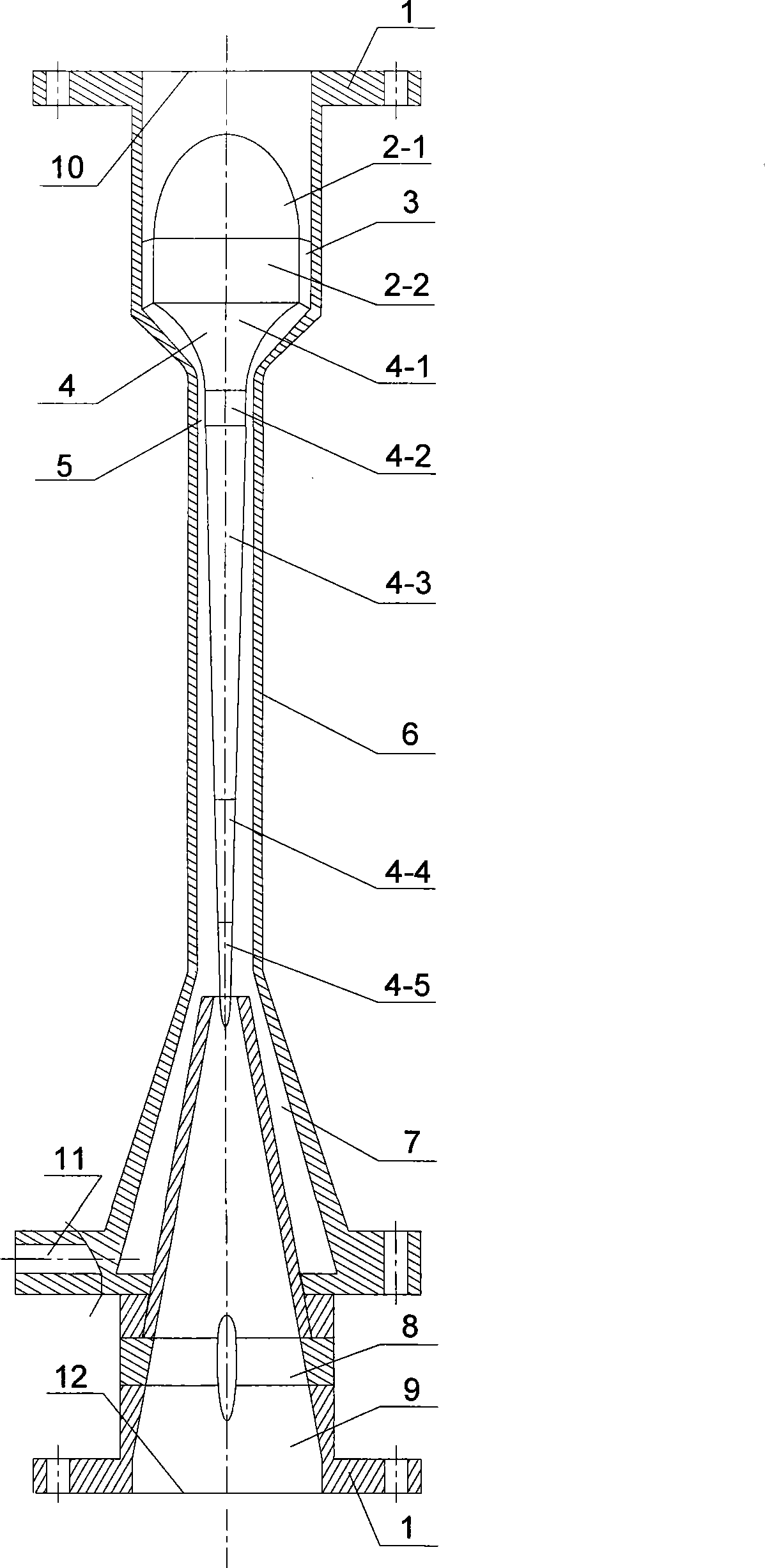
[0028] refer to figure 1 . The transonic controllable vortex gas dehumidification device of the present invention comprises a housing 6 with an airflow inlet 10 on the upper end, a liquid discharge port 11 and an exhaust port 12 on the lower end, a connecting flange 1 is arranged on the upper end of the housing, and the inner diameter of the housing 6 is 20mm.

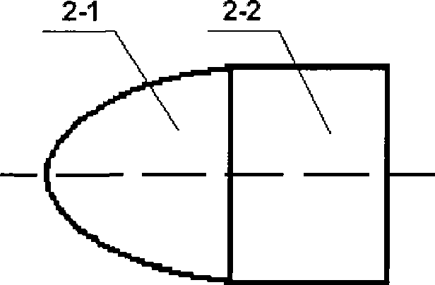
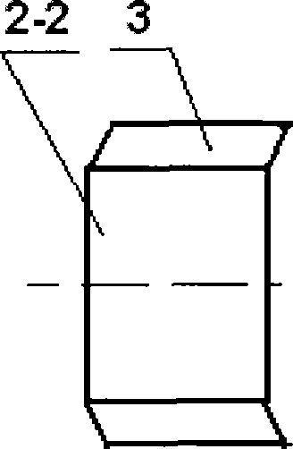
[0029]The shell 6 is composed of an inlet pipe 6-1, a conical reducer 6-2, a straight pipe 6-3 and a conical expander 6-4, and a blunt body rectifier 2 is fixed inside the inlet pipe 6-1. The rectifier 2 is composed of an ellipsoidal head 2-1 and a cylindrical base 2-2, and a vortex generator 3 composed of stationary vanes is fixed around the cyl...


PUM


Abstract

A transonic speed controllable vortex gas dehumidifier adopts a mode generating vortex through a static cascade of a vortex generator. A shell of the dehumidifier and a vortex controller form an annular jet tube, the vortex intensity of gas-liquid phase flows is controlled by changing the flow passage area of an annular space to realize the condensation and separation process of components and achieve the purpose for improving the separation efficiency and lowering the flow loss by combining a high-effective back-pressure device. The dehumidifier can change the mode generating vortex, control the change of the vortex intensity in the processes of component condensation, component separation, back pressure, and the like, improve the component separation efficiency and reduce the total pressure loss. The invention has the advantages of no addition of medical agent, low weight, compact space structure, small occupied area, low cost, unmanned operation, high inherent safety, and the like, thereby having wide application prospect in the fields of the separation and the liquefaction of high-pressure mixed gases, and the like.

Description

technical field [0001] The invention relates to the technical field of gas drying treatment, in particular to the technical field of dehumidification of water vapor and heavy hydrocarbons in natural gas. It is a multi-component gas separation and dehumidification device, specifically a transonic controllable vortex gas dehumidification device that removes one or more components in the mixed gas flow. Background technique [0002] The transonic controllable vortex gas dehumidification device can be applied in many industrial technical fields, such as dehydration and dehydrocarbon treatment of oil and gas, gas treatment in various fields such as environment, chemical industry, and building materials. [0003] Dehumidification of high pressure gases is a frequently encountered task in industrial processes. For example, the natural gas extracted from the formation is often mixed with liquid water and water vapor, condensate, heavy hydrocarbon gas, solid particles, etc. Before t...

Claims


Application Information

Patent Timeline
IPC IPC(8): B01D53/26B01D45/16
Inventor 王道富徐永高张书平白博峰
Owner PETROCHINA CO LTD
Learn More