
Sintered gear

A technology of powder metallurgy and gears, which is applied in the direction of belts/chains/gears, components with teeth, portable lifting devices, etc., can solve the problems of low mechanical strength, reduce porosity, expand the application range, and improve the strength of broken teeth Effect

Inactive Publication Date: 2009-08-26
MIBA SINTER AUSTRIA
View PDF3 Cites 4 Cited by
  • Summary
  • Abstract
  • Description
  • Claims
  • Application Information

AI Technical Summary

Problems solved by technology

However, limited by the manufacturing conditions, the sintered parts without additional treatment have low mechanical strength due to residual porosity

Method used


Image

  • Sintered gear

Examples


Embodiment Construction

[0019] First of all, it should be understood that in the different embodiments, the same parts have the same reference numerals or the same component names, wherein the disclosure contained in the entire description can be transferred to the same drawings with the same meaning. mark or the same component name on the part. The position parameters selected in the description, such as: top, bottom, side, etc., are related to the figure directly drawn and described, and when the position is changed, they are also transferred to the new position according to the meaning. Furthermore, the individual features or combinations of features of the various embodiments shown and described can also represent independent, imagined or inventive solutions in their own right.

[0020] All data in the numerical range in the specific description should be understood as such, it includes any sub-range and all sub-ranges, for example, data 1 to 10 should be understood as including all sub-ranges fr...


PUM

PropertyMeasurementUnit
surface roughnessaaaaaaaaaa

Abstract

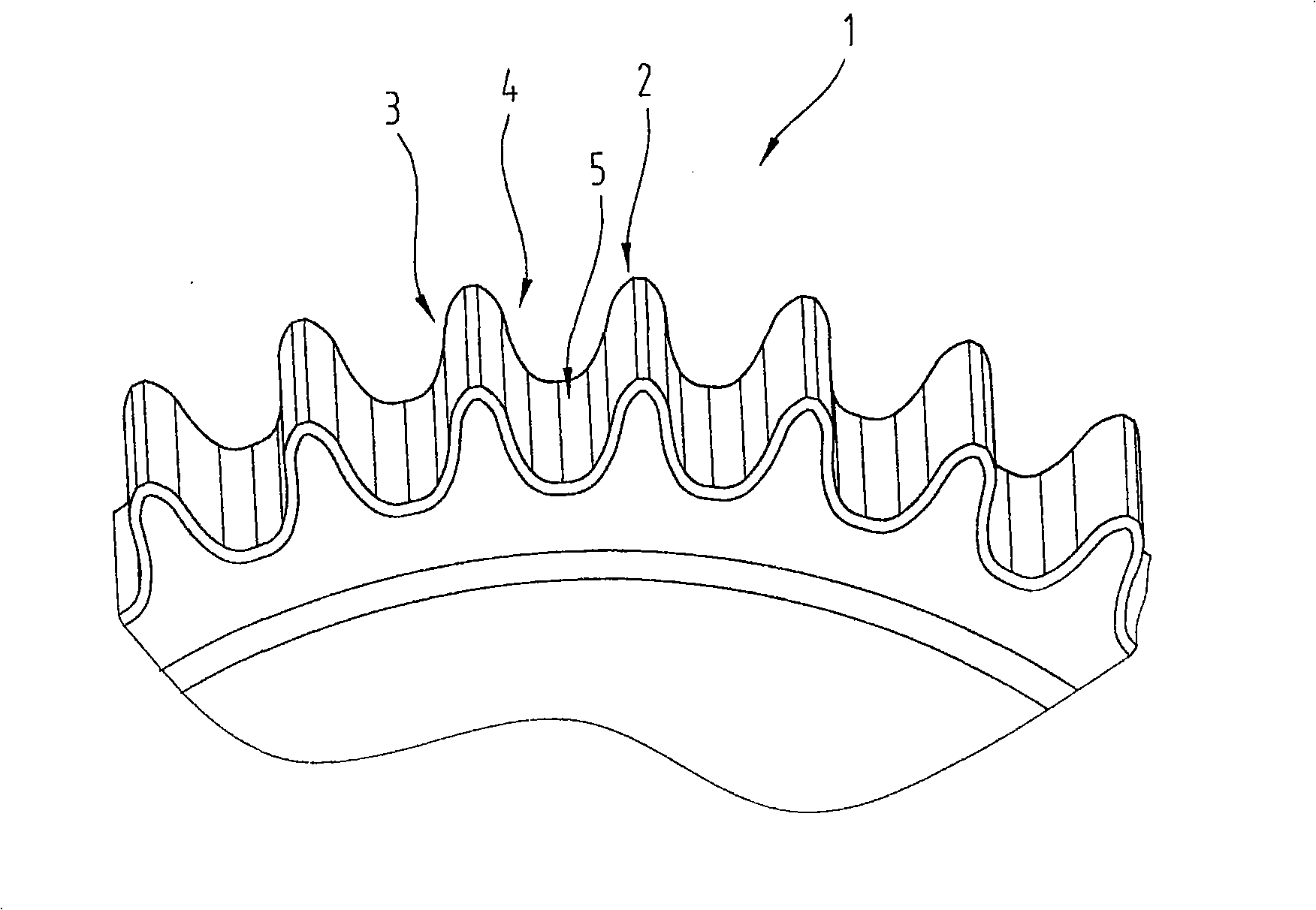
The invention relates to a sintered gear (1) with teeth (2), between which a tooth base (5) is respectively formed. The tooth base (5) has a surface which is subjected to a thermo-mechanical finishing process and a surface roughness with an arithmetical mean roughness value Ra, measured in accordance with DIN EN ISO 4287, selected fr om a range with a lower limit of 0.2 .mu.m and an upper limit of 2.0 .mu.m.

Description

technical field [0001] The invention relates to a powder metallurgy gear and a manufacturing method for improving its mechanical strength. There are tooth bottoms formed between the teeth of the powder metallurgy gear respectively. Background technique [0002] Components produced by conventional metallurgy are increasingly being replaced by components produced by powder metallurgy, especially because the latter can be easily produced with complex geometries. However, limited by the manufacturing conditions, the sintered parts without additional treatment have low mechanical strength due to residual porosity. On the one hand, residual porosity is desirable, for example for sintered components used in lubrication systems. In this case, the pores can act as storage containers for the lubricant. In order to improve the mechanical strength, various methods exist in the prior art to reduce the residual porosity. The gear surface is compacted, for example by radial pressing or...

Claims


Application Information

Patent Timeline
Patent Type & Authority Applications(China)
IPC IPC(8): F16H55/17F16H55/08B22F5/08
CPCB22F2003/247B22F5/08B22F2003/248B22F2003/241F16H55/06B22F2998/10B22F3/24C22C33/0257Y10T29/49467Y10T428/211B22F3/02B22F3/10B22F3/164
Inventor 赫伯特·施密德卡尔·迪金格尔沃尔夫冈·西斯尔
Owner MIBA SINTER AUSTRIA
Learn More