Low loss adjustable band-pass filter based on left hand characteristic
A filter and low-loss technology, applied in the field of low-loss tunable band-pass filters, can solve the problems affecting the application performance of left-handed materials, the difficulty of tunable left-handed materials, and the increase of structural complexity, achieving mature production technology and low price. , the effect of simple structure
- Summary
- Abstract
- Description
- Claims
- Application Information
AI Technical Summary
Problems solved by technology
Method used
Image
Examples
Embodiment 1
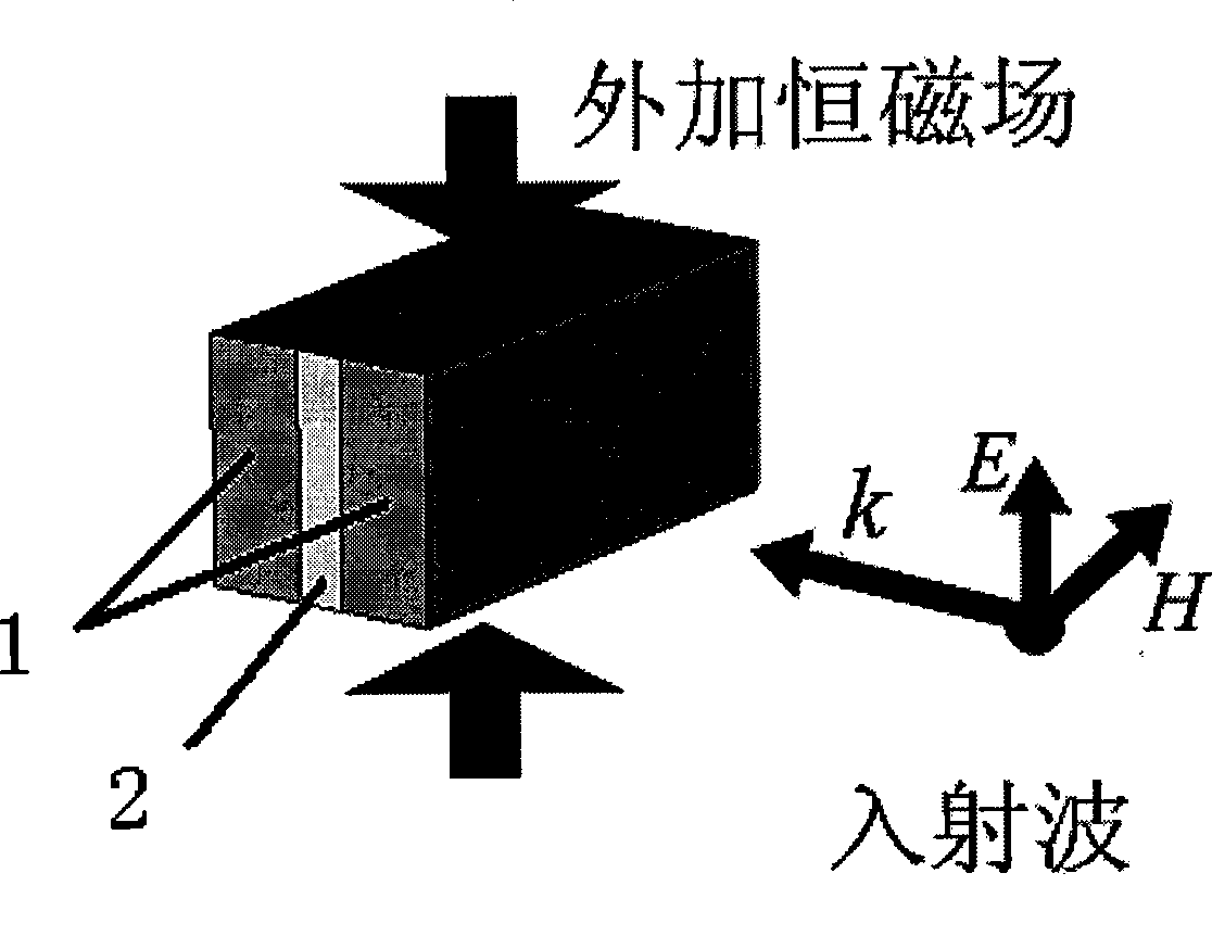
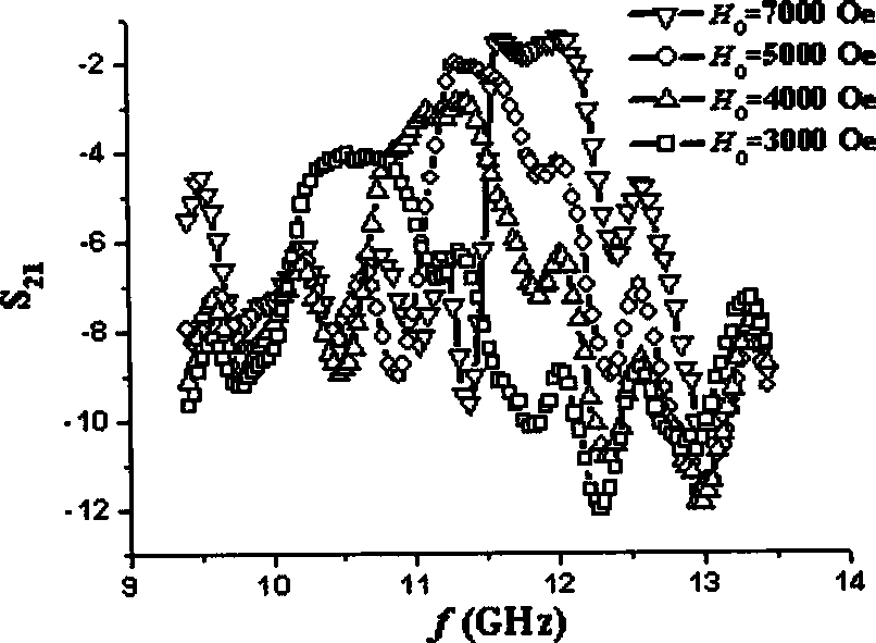
[0015] Ba was prepared using standard solid-phase ceramic techniques 2 co 2 Fe 12 o 22 Ferrite substrate, the sintered ferrite is finely processed into a sheet sample with a size of 22mm×10mm×4mm, and Al with a size of 22mm×10mm×1mm is inserted between the two ferrites. 2 o 3 As a dielectric layer, its magnetic permeability is 1, magnetic loss is less than 0.0001, dielectric constant is 6, dielectric loss is 0.001, and resistivity is higher than 1×10 12 Ωcm, two ferrites and Al 2 o 3 The layers fit closely together to form a sandwich filter. The filter is loaded into a standard rectangular waveguide test, using figure 1 The method shown applies an external magnetic field to the filter, and uses a vector network analyzer to test its microwave filtering characteristics. The results obtained are as follows figure 2 shown. The obtained microwave passband width is about 1GHz, and the insertion loss can be as low as below 1dB. The operating frequency band of the microwave...
Embodiment 2
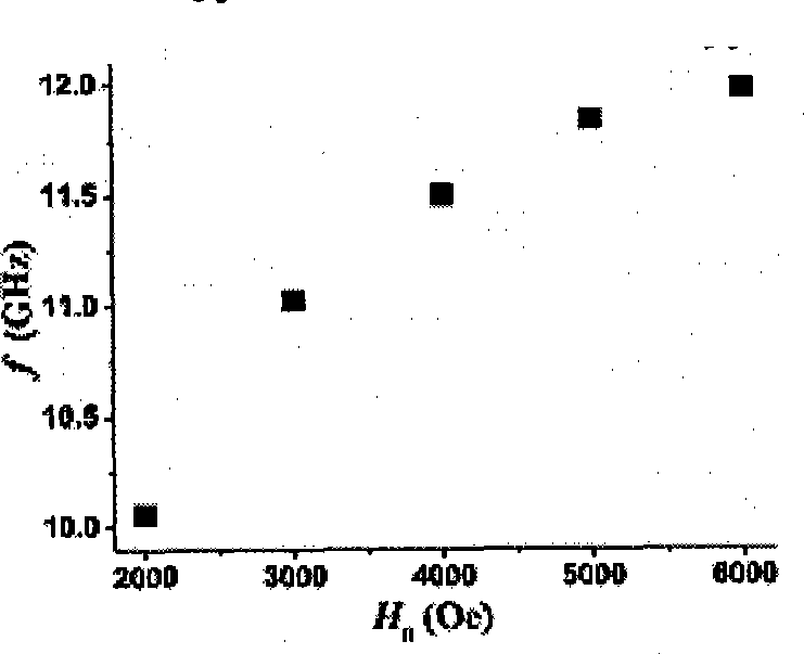
[0017] Ba was prepared using standard solid-phase ceramic techniques 2 co 2 Fe 12 o 22 Ferrite substrate, the sintered ferrite is finely processed into a sheet sample with a size of 22mm×10mm×4mm, and Teflon with a size of 22mm×10mm×2mm is inserted between the two ferrites as a dielectric layer. 1, the magnetic loss is less than 0.0001, the dielectric constant is 2.6, the dielectric loss is 0.0001, and the resistivity is higher than 1×10 12 Ωcm, two ferrites and Teflon layers are closely bonded to form a sandwich structure filter. The filter is loaded into a standard rectangular waveguide for testing, and its microwave filtering characteristics are obtained. The microwave passband width is about 1GHz, and the insertion loss can be as low as below 1dB. The working frequency band of the microwave passband increases with the increase of the external magnetic field strength, and the change law of the passband center frequency with the external magnetic field is as follows: im...
Embodiment 3
[0019] Ba was prepared using standard solid-phase ceramic techniques 2 co 1.6 Cu 0.4 Fe 12 o 22 Ferrite substrate, the sintered ferrite is finely processed into a sheet sample with a size of 22mm×10mm×4mm, and organic glass is inserted between the two ferrites as a dielectric layer. The magnetic permeability is 1 and the magnetic loss is less than 0.0001, the dielectric constant is 4, the dielectric loss is 0.01, and the resistivity is higher than 1×10 12 Ωcm, two ferrites and plexiglass are closely bonded to form a sandwich structure filter. Change the dielectric layer in the sandwich structure, use 22mm×10mm×0.1mm, 22mm×10mm×1mm, 22mm×10mm×2mm, 22mm×10mm×4mm plexiglass and ferrite layer to composite, and obtain a series of test samples, The microwave transmission properties of these samples were tested, and the results were as follows Figure 4 shown. As the thickness of the dielectric layer increases, the passband width of the filter decreases and the insertion loss ...
PUM
| Property | Measurement | Unit |
|---|---|---|
| Resistivity | aaaaa | aaaaa |
Abstract
Description
Claims
Application Information
 - R&D
- Intellectual Property
- Life Sciences
- Materials
- Tech Scout
- Unparalleled Data Quality
- Higher Quality Content
- 60% Fewer Hallucinations
Browse by: Latest US Patents, China's latest patents, Technical Efficacy Thesaurus, Application Domain, Technology Topic, Popular Technical Reports.
© 2025 PatSnap. All rights reserved.Legal|Privacy policy|Modern Slavery Act Transparency Statement|Sitemap|About US| Contact US: help@patsnap.com


