
Diamond opposite vertex anvil inflating method and device

A technology of diamond topping and inflating device, which is applied in the process of applying ultra-high pressure and other directions, can solve the problems of large consumption of inflatable body, complex pressure device and remote pressurizing equipment, etc., to improve the success rate of experiments, and the method is simple and easy. The effect of running, less consumption

Inactive Publication Date: 2009-08-05
INST OF PHYSICS - CHINESE ACAD OF SCI
View PDF0 Cites 4 Cited by
  • Summary
  • Abstract
  • Description
  • Claims
  • Application Information

AI Technical Summary

Problems solved by technology

[0002] The existing inflation method of the diamond counter anvil (DAC) device mainly uses high pressure (thousands of atmospheres) to inflate the gas to be inflated into the diamond counter anvil device. The inflation process requires complex pressure devices and remote charging. Pressure equipment, and the inflation process of this method needs to consume a large amount of gas to be inflated

Method used


Image

  • Diamond opposite vertex anvil inflating method and device
  • Diamond opposite vertex anvil inflating method and device
  • Diamond opposite vertex anvil inflating method and device

Examples


Embodiment 1

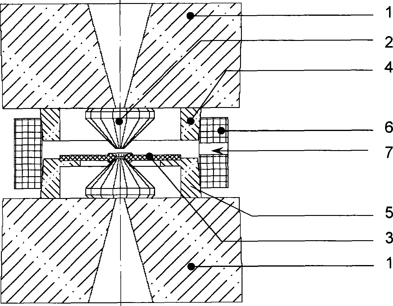
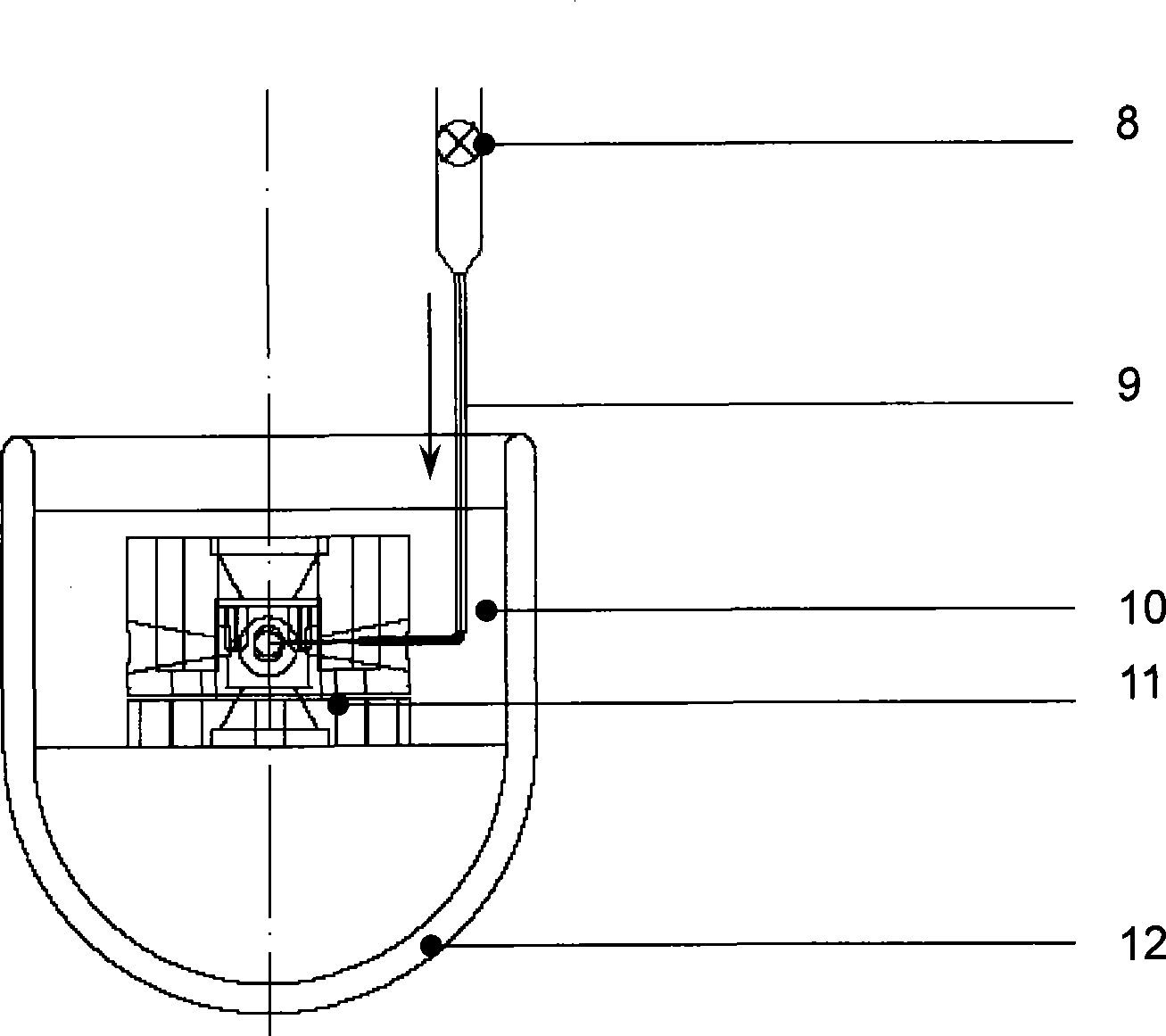
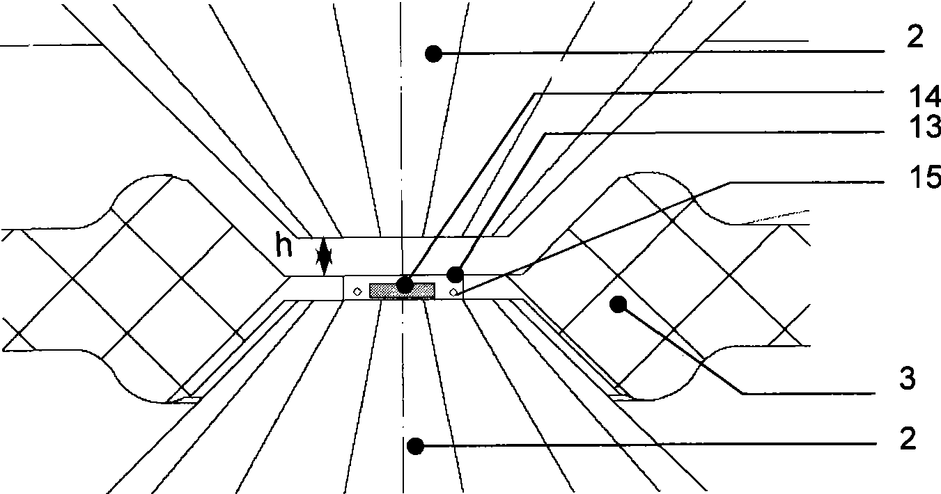
[0025] like Figure 1-3 As shown, the diamond anvil inflation device of the present invention includes a diamond anvil body, a gas introduction device, a sealing device and a cooling device, and the sealing device includes a gasket 3, a plastic connector 6 and an upper and a lower sealing frame 4, 5. The diamond anvil body includes a diamond anvil 2 and a spacer 1 . The diamond anvil 2 is fixed on the block 1, and the upper and lower sealing frames 4, 5 are arranged on the block 1, and the diamond anvil 2 is wrapped therein. The upper and lower sealing frames 4 and 5 are connected by a plastic connector 6, the plastic connector 6 is made of elastic and self-lubricating materials, through the upper and lower sealing frames 4, 5 and the plastic connector 6, the upper and lower A sealed cavity is formed between the pads 1 . A gasket 3 is arranged on the lower sealing frame 5 to divide the sealing chamber into upper and lower parts. The gasket 3 has been pre-pressed and a sample...

Embodiment 2

[0026] Embodiment 2: Inert gas Ar is filled in the DAC sample cavity by using a low-temperature cooling and gas charging device.

[0027] The preparation method of this embodiment comprises the following steps:

[0028] 1) Fix the gasket 3 pre-compressed to an appropriate thickness and drill holes between the opposing anvils of the DAC device and record the zero position of the compression screw. We use a T301 stainless steel sheet with an initial thickness of 250 μm as a gasket. When the diameter of the end face of the diamond anvil is 500 μm, the final thickness of the pre-pressed gasket 3 is not greater than 40 μm, and the diameter of the sample chamber 13 is about 1 / 1 of the diameter of the end face of the diamond anvil. 3. A sample sheet 14 of appropriate size and thickness and a pressure mark 15 are placed in the sample cavity 13 according to the needs of the experiment. Here we use ruby ​​as the pressure mark.

[0029] 2) Since the gas to be inflated is high-purity Ar...


PUM


Abstract

The invention discloses a method and a device for charging air for a diamond butting pressure anvil. The air charging method comprises: making gas highly dense and even liquefied by a low-temperature cooling means; then making the gas enter sealing cavities among diamond pads in a cooled DAC device, and ensuring the gas fully fills the cavity at the pressure slightly higher than the atmospheric pressure; tightly locking the DAC device through external force; and sealing the gas to be charged into a sample cavity. The device for charging air for the diamond butting pressure anvil comprises a diamond butting pressure anvil body, a gas introducing device, a sealing device and a cooling device. The method can make air flow in the sample cavity more stable, can obviously improve experiment success rate and can greatly reduce unnecessary gas loss at the same time.

Description

technical field [0001] The invention relates to a gas charging technology for a diamond-to-top anvil device, in particular to a method and a device for gas charging a low-temperature rare gas. Background technique [0002] The existing inflation method of the diamond counter anvil (DAC) device mainly uses high pressure (thousands of atmospheres) to inflate the gas to be inflated into the diamond counter anvil device. The inflation process requires complex pressure devices and remote charging. Pressure equipment, and the inflation process of this method needs to consume a large amount of gas to be inflated. Contents of the invention [0003] The purpose of the present invention is to utilize simple and feasible experimental means to fill gas in the diamond counter anvil device. The invention adopts low-temperature cooling means to make the gas highly dense, and then enters the sealed cavity between the diamond pads, and ensures that the gas is filled with the cavity at a p...

Claims


Application Information

Patent Timeline
Patent Type & Authority Applications(China)
IPC IPC(8): B01J3/06
Inventor 游淑洁陈良辰靳常青
Owner INST OF PHYSICS - CHINESE ACAD OF SCI
Learn More