


Quick Research
Generate reliable direction feasibility study reports for your R&D in just a few steps.

Technical Q&A
Discover and master advanced knowledge NOW. Basics, ideas, possibilities, all at once.

Find Solutions
As an expert in R&D theories, this can generate solutions to your technical problems instantly.

Evaluate Feasibility
Analyze your overall solution with one click, know your potential R&D risks in advance.

Monitor Landscape
Get weekly tech updates, stay abreast of the latest tech innovations and key insights.
Receiver, integrated circuit, and reception method
A receiving device and technology for receiving signals, which are applied to electrical components, multiplexing communication, orthogonal multiplexing systems, etc., can solve problems such as difficulty in reducing the demodulation error of the equalizer 106, and achieve accurate estimation. Effect
- Summary
- Abstract
- Description
- Claims
- Application Information
AI Technical Summary
Problems solved by technology
Method used
Image


Examples
no. 1 Embodiment approach
[0114] Hereinafter, a first embodiment of the present invention will be described with reference to the drawings.
[0115]
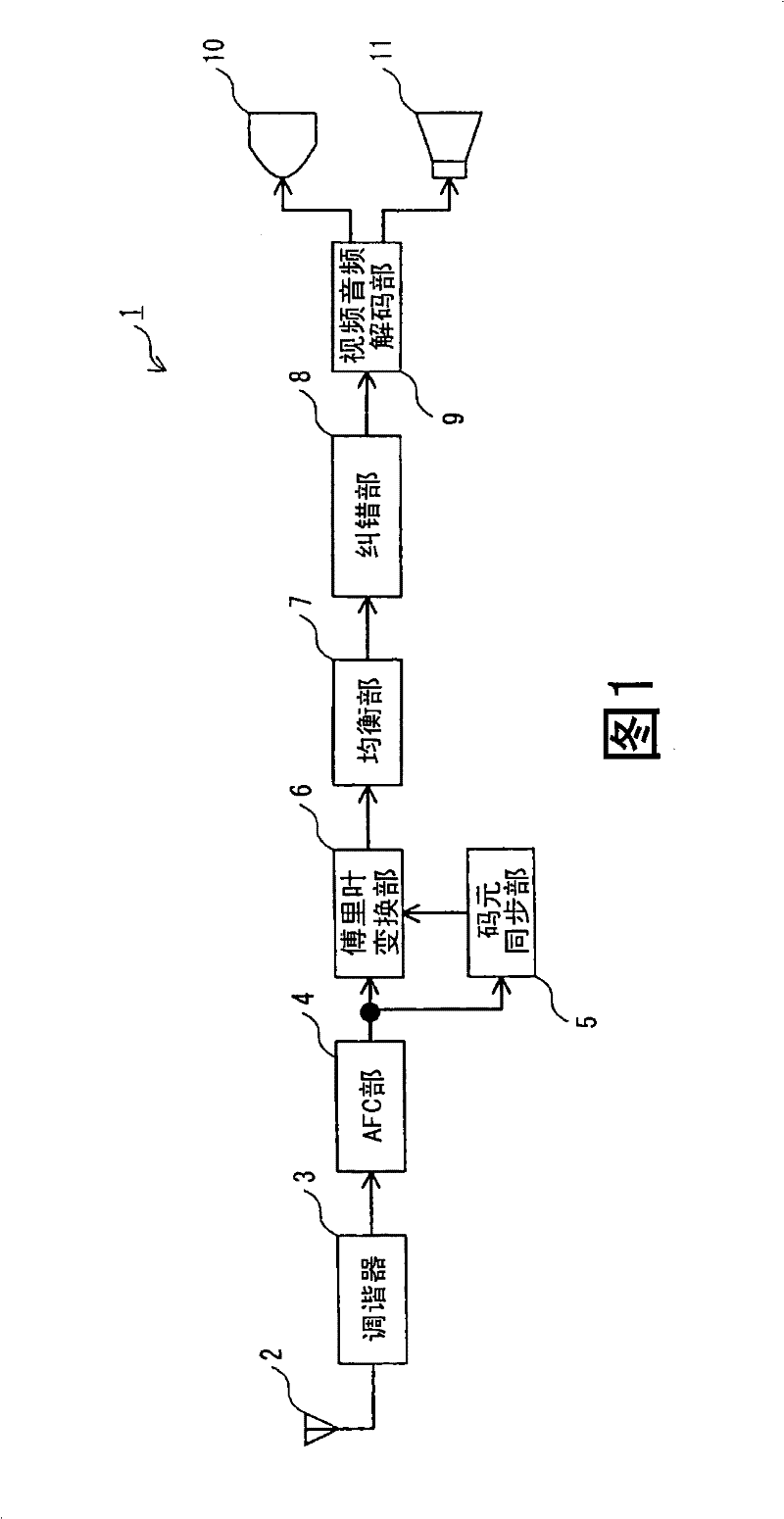
[0116] refer to figure 1 The configuration of the receiving device 1 according to this embodiment will be described. figure 1 It is a configuration diagram of the receiving device 1 according to the present embodiment, and is an example of a configuration of a receiving device that receives terrestrial digital television broadcasting using the OFDM transmission method.
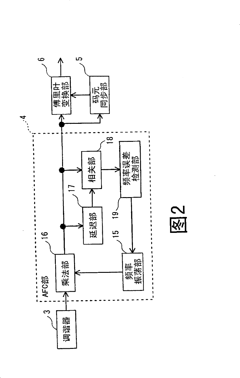
[0117] The receiving device 1 includes an antenna 2, a tuner 3, an AFC unit 4, a symbol synchronization unit 5, a Fourier transform unit 6, an equalization unit 7, an error correction unit 8, a video and audio decoding unit 9, a display unit 10, and a speaker 11 .
[0118] The antenna 2 receives broadcast radio waves from a not-shown broadcast station via a channel, and outputs the received broadcast radio waves to the tuner 3 .
[0119] Tuner 3 selects a desired broadcast wave fr...
no. 2 Embodiment approach
[0215] Hereinafter, a second embodiment of the present invention will be described with reference to the drawings.
[0216] Among them, the filter control unit 27a of the present embodiment that controls the frequency shift of the frequency transfer characteristic of the symbol interpolation filter 24 is different from the filter control unit 27 of the first embodiment, and the rest is substantially the same as the first embodiment.
[0217]
[0218] refer to Figure 9 The configuration of the filter control unit 27a in this embodiment will be described. Figure 9 It is a block diagram of the filter control part 27a of this embodiment. However, in this embodiment, members having substantially the same functions as those in the first embodiment are given the same symbols as in the first embodiment, and the description of the first embodiment can be applied, so the description is omitted.
[0219] The filter control unit 27a has a CP signal extraction unit 41, a CP signal ge...
no. 3 Embodiment approach
[0246] Hereinafter, a third embodiment of the present invention will be described with reference to the drawings.
[0247] Among them, the filter control unit 27b of the present embodiment that controls the frequency shift of the frequency transfer characteristic of the symbol interpolation filter 24 is different from the filter control unit 27 of the first embodiment, and the rest is substantially the same as the first embodiment.
[0248]The filter control unit 27 of the first embodiment calculates the channel characteristic for each symbol using the CP signal included in the Fourier-transformed received signal, and controls the frequency transfer characteristic of the symbol interpolation filter 24 using the calculated channel characteristic. frequency shift.
[0249] However, the filter control unit 27b of the present embodiment uses the TMCC (Transmission and Multiplexing Configuration Control, transmission and multiplexing configuration control) signal contained in the r...
PUM
 Abstract
Description
Claims
Application Information
 - R&D Engineer
- R&D Manager
- IP Professional
- Industry Leading Data Capabilities
- Powerful AI technology
- Patent DNA Extraction
Browse by: Latest US Patents, China's latest patents, Technical Efficacy Thesaurus, Application Domain, Technology Topic, Popular Technical Reports.
© 2024 PatSnap. All rights reserved.Legal|Privacy policy|Modern Slavery Act Transparency Statement|Sitemap|About US| Contact US: help@patsnap.com