
Smooth and steady workstation of vertical lathe

A vertical lathe and workbench technology, applied in the field of lathes, can solve problems such as difficulty in ensuring the parallelism of tool holders and affecting the machining accuracy of workpieces, and achieve the effects of stable work, improved wear resistance, and high rotation accuracy

Inactive Publication Date: 2009-07-15
大连国丰机床有限公司
View PDF0 Cites 3 Cited by
  • Summary
  • Abstract
  • Description
  • Claims
  • Application Information

AI Technical Summary

Problems solved by technology

When working, the vertical tool holder and side tool holder are fed to a suitable position, and the workpiece to be processed is placed on the workbench for workpiece processing. At present, the base of the vertical lathe workbench is connected to the main shaft, which rotates under the drive of the main shaft and works at high speed. The table top is prone to radial or end surface runout, especially the radial movement is more obvious, so it is difficult to ensure the parallelism of the tool holder or the tool holder ram relative to the rotation axis of the worktable when moving, thus affecting the machining accuracy of the workpiece

Method used


Image

  • Smooth and steady workstation of vertical lathe
  • Smooth and steady workstation of vertical lathe

Examples


Embodiment Construction

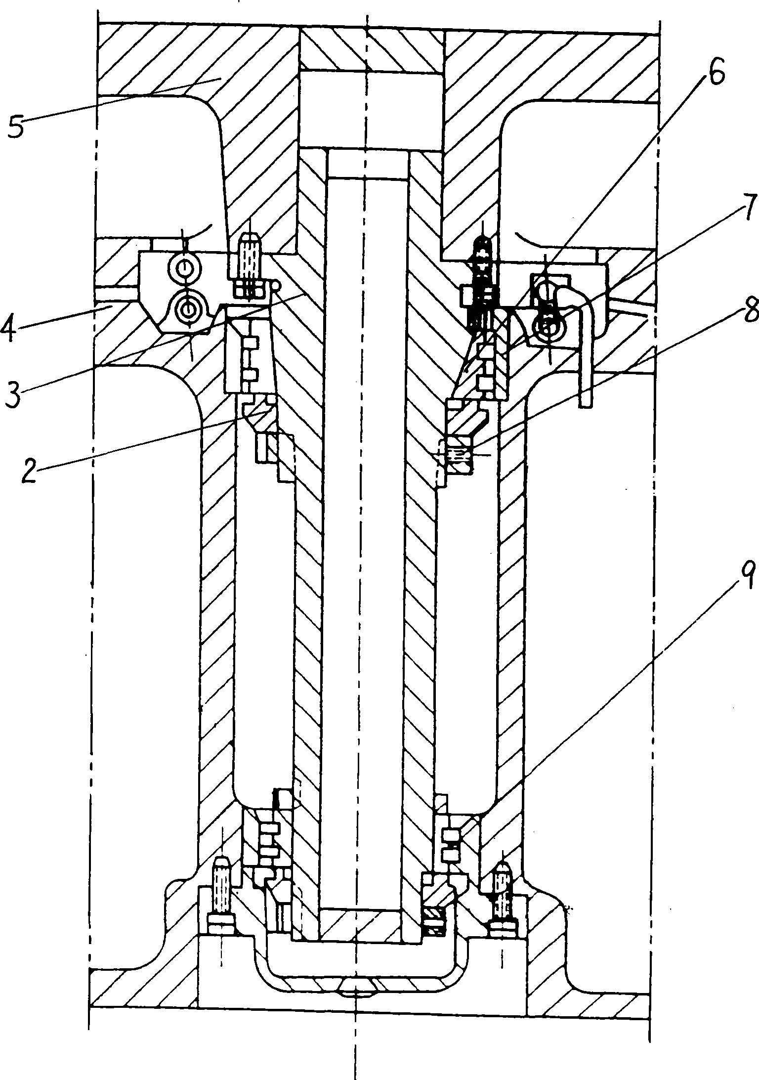
[0012] Such as figure 1 The vertical lathe workbench shown involves a turntable 5 and a base 4, and the bottom surface of the turntable 5 and the upper surface of the base 4 are compounded with a zinc alloy wear-resistant plate 1 to increase the service life of the workbench. The main shaft 3 is set in the base 4 through the bearing, the upper end of the main shaft 3 is fixedly connected with the turntable 5, the lower end of the main shaft is equipped with a bearing 9, the bottom end of the main shaft 3 is connected with the reducer, and the outer diameter of the joint between the main shaft 3 and the base 4 has a taper. 3182100 type double-row cylindrical roller bearing 7 with tapered inner ring 6 is installed at the place with taper. Adjusting nut 8 is set on the main shaft 3. The adjusting nut 8 is close to the small inner diameter end of bearing 7. Adjusting nut 8 and tapered bearing 7 Adjusting spacers 2 are installed between them.

[0013] When the present invention is...


PUM


Abstract

The invention relates to a lathe, in particular to a vertical lathe worktable which comprises a worktable turntable and a base, wherein a mainshaft is sleeved in the base through a bearing, the upper end of the mainshaft is fixedly connected with the turntable, and the lower end of the mainshaft is connected with a speed reducer; the outer diameter at the joint part of the mainshaft and the base is provided with a taper, a bearing with an inner ring provided with a taper is assembled at the mainshaft with the taper, and an adjusting nut is sleeved on the mainshaft and is close to the small internal diameter end of the bearing. In the invention, the mainshaft of the worktable is directly started by a main motor and dynamically braked, bearings are arranged at the upper part and the lower part of the mainshaft, and a radial clearance of the bearing can be adjusted as the inner ring of the bearing is provided with the taper; the bearings of the mainshaft are adjusted aiming at reducing the radial clearance of the bearings; and as the bearings of the mainshaft is provided with the tapers radially, the inner rings of the bearings can produce the radial deformation when being axially adjusted so as to adjust the combined clearance among a bearing roller, the inner rings and outer rings of the bearings, thereby ensuring that the mainshaft stably works under high rotating speed and high precision, and having large bearing capacity.

Description

1. Technical field: [0001] The invention relates to lathes, in particular to worktables for vertical lathes. 2. Background technology: [0002] The single-column vertical lathe is an ordinary lathe with a vertical tool holder and a side tool holder, which is suitable for high-speed steel tools and carbide tools to process various ferrous metals, non-ferrous metals and some non-metallic materials, such as turning internal and external Cylindrical and flat surfaces; turning internal and external conical surfaces; grooving; drilling, reaming and reaming. When working, the vertical tool holder and side tool holder are fed to a suitable position, and the workpiece to be processed is placed on the workbench for workpiece processing. At present, the base of the vertical lathe workbench is connected to the main shaft, which rotates under the drive of the main shaft and works at high speed. The table top is prone to radial or end surface runout, especially the radial movement is mor...

Claims


Application Information

Patent Timeline
Patent Type & Authority Applications(China)
IPC IPC(8): B23B25/00B23Q1/74
Inventor 张国良
Owner 大连国丰机床有限公司
Learn More