Heat dissipating wiring board and method for manufacturing same
A manufacturing method and technology for wiring boards, which are applied in the manufacture of printed circuits, removal of conductive materials by discharge methods, and removal of conductive materials by chemical/electrolytic methods, etc., can solve problems such as narrowing and poor fluidity.
- Summary
- Abstract
- Description
- Claims
- Application Information
AI Technical Summary
Problems solved by technology
Method used
Image

Examples
no. 1 approach
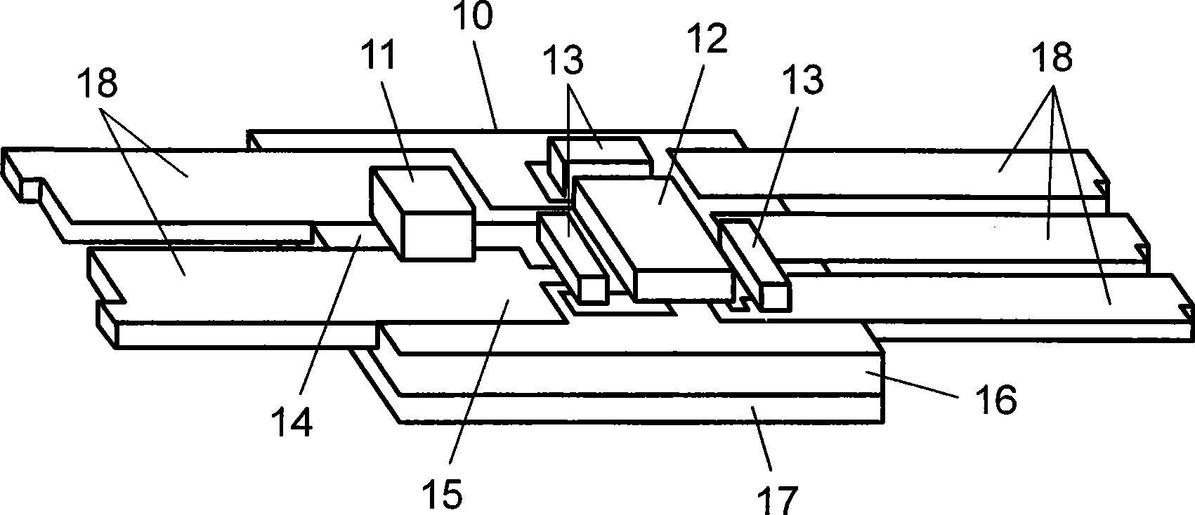
[0072] In the first embodiment, a case where heat generating components are adjacently mounted at a high density will be described. Here, as heat-generating components, there are electronic components such as power semiconductors (power transistors, power FETs, CPUs, etc.), microtransformers, and LEDs. The miniaturization of such electronic components contributes to the miniaturization of equipment. However, as such electronic components are miniaturized, or the mounting method (for example, packaging method) of electronic components becomes smaller (and further, during bare chip mounting, etc.), heat generation (or heat dissipation) becomes a more important issue. Therefore, in the first embodiment, an LED is selected as an example of a heat-generating component and described in detail.
[0073] In the first embodiment, a heat radiation wiring board 10 for a large current of 100 A (ampere) as an LED mounting substrate will be described as an example.
[0074] figure 1 An ...
no. 2 approach
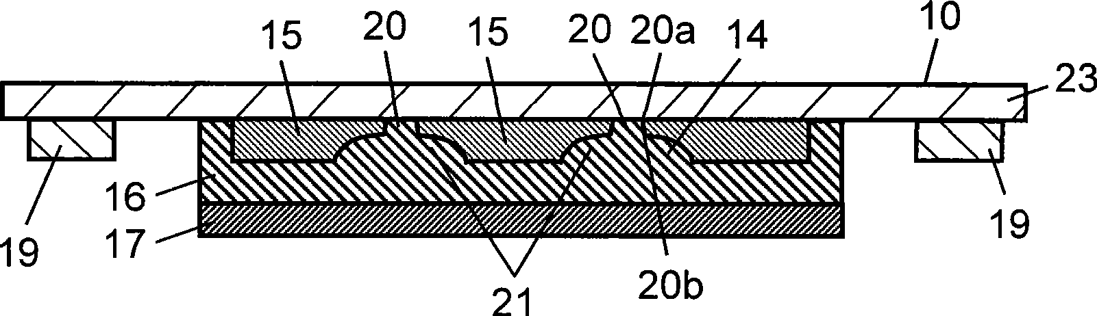
[0165] Second, use Figure 5 , and the second embodiment will be described. In addition, the same reference numerals are assigned to the same parts as those in the drawings used in the description of the first embodiment.
[0166] The second embodiment corresponds to, for example, the case where the expanded groove 21 is formed by etching or machining, and then the fine groove 20 is formed by laser.
[0167] Figure 5 It is a schematic cross-sectional view showing the state after the oxide film 24 is formed on the surface of the fine groove 20 . Here, as an insulating film, by forming an oxide film 24 on the surface of the fine groove 20, the insulating effect of the combined use of an insulating film can be enhanced. As the oxide film 24, a metal oxide film formed by oxidizing the surface of the metal wiring board 15 can be used.
[0168] exist Figure 5 Among them, a part of the through groove 14 consists of a fine groove 20 having an opening 20a on the upper surface of...
no. 3 approach
[0180] Second, use Figure 6 to Figure 9 , and the third embodiment will be described.
[0181] Figure 6 It is a schematic sectional view explaining the case where the through groove 14 is formed by performing groove processing from both sides of the metal wiring board 15 . In addition, the same reference numerals are attached to the same parts as those in the drawings used in the description of the first embodiment and the second embodiment.
[0182] First, a copper or aluminum plate or a laminate or composite plate of these materials is prepared. In addition, it is also possible to use a sheet material in which necessary parts are pressed by pressurization. And, let this be the metal wiring board 15 .
[0183] Secondly, if Figure 6 As shown, from the back side of the metal wiring board 15, the expanded groove 21 is formed by etching or laser processing as indicated by an arrow 25a. Next, from the surface side of the metal wiring board 15, as shown by the arrow 25b, t...
PUM
 Abstract
Description
Claims
Application Information
 - Generate Ideas
- Intellectual Property
- Life Sciences
- Materials
- Tech Scout
- Unparalleled Data Quality
- Higher Quality Content
- 60% Fewer Hallucinations
Browse by: Latest US Patents, China's latest patents, Technical Efficacy Thesaurus, Application Domain, Technology Topic, Popular Technical Reports.
© 2025 PatSnap. All rights reserved.Legal|Privacy policy|Modern Slavery Act Transparency Statement|Sitemap|About US| Contact US: help@patsnap.com