Polarizing plate, liquid crystal display and protective film
A technology of liquid crystal display devices and polarizers, which is applied in the direction of identification devices, polarizing elements, instruments, etc., can solve the problems of polarizer polarization decrease, film shrinkage, etc., and achieve improved scratch resistance, less light leakage, and improved appearance Effect
- Summary
- Abstract
- Description
- Claims
- Application Information
AI Technical Summary
Problems solved by technology
Method used
Image
Examples
Embodiment
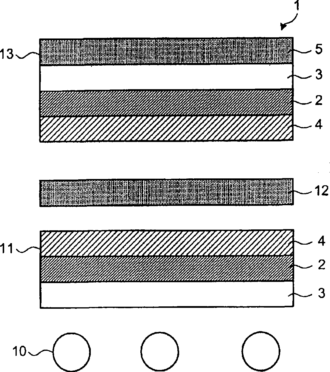
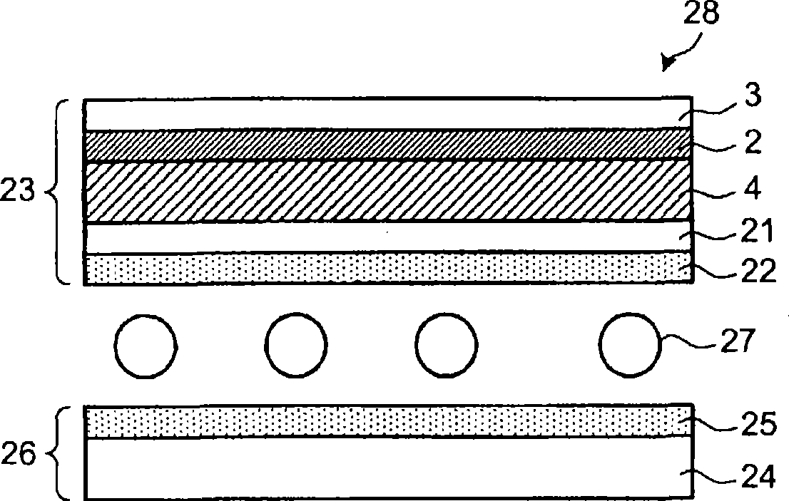
[0211] In the following examples, the polarizing plate includes a polarizer (P), an exit-side protective film (first protective film (A)) attached to the exit side of the polarizer (P), ), the incident side protective film (second protective film (B)) on the incident side, the hard coat layer (H) laminated on the viewing side surface of the output side protective film (first protective film (A)), Low refractive index (anti-reflection) layer (L) on the outer surface of layer (H). In all the Examples and Comparative Examples, the polarizer (P), the hard coat layer (H) and the low-refractive-index layer (L) all used products of the same composition described later having the same thickness.
[0212] It will be described in detail later. In embodiment 1-1, as the first protective film, a polymethyl methacrylate (PMMA) resin layer-low hardness polymethyl methacrylate (R-PMMA) resin layer- A laminated film (A1) composed of three layers of a polymethyl methacrylate (PMMA) resin laye...
manufacture example 1
[0219] (Manufacturing example 1: Production of polarizer)
[0220] A polyvinyl alcohol film with a refractive index of 1.545 at a wavelength of 380nm, a refractive index of 1.521 at a wavelength of 780nm, and a thickness of 75 μm was uniaxially stretched to 2.5 times. ℃ aqueous solution for 240 seconds, and then immersed in an aqueous solution containing boric acid 70g / L and potassium iodide 30g / L, while uniaxially stretching to 6.0 times and maintaining for 5 minutes. Finally, it was dried at room temperature for 24 hours to obtain a polarizer (P) having an average thickness of 30 μm and a degree of polarization of 99.95%.
manufacture example 2
[0221] (Manufacturing example 2: Preparation of material for forming hard coat layer (H))
[0222] Mix 30 parts of 6-functional urethane acrylate oligomer, 40 parts of butyl acrylate, 30 parts of isophorone methacrylate and 10 parts of 2,2-diphenylethane-1-one with a homogenizer Then, mix 40% methyl isobutyl group of antimony pentoxide particles (average particle diameter 20nm, hydroxyl group is combined with antimony atom appearing on the surface of pyrochlore structure, the combination ratio is 1 antimony atom combined with a hydroxyl group) A ketone solution was mixed in such a ratio that the weight of antimony pentoxide fine particles accounted for 50% by weight of the total solid content of the composition for forming a hard coat layer to prepare a material for forming a hard coat layer (H).
PUM
| Property | Measurement | Unit |
|---|---|---|
| coating thickness | aaaaa | aaaaa |
| glass transition temperature | aaaaa | aaaaa |
| glass transition temperature | aaaaa | aaaaa |
Abstract
Description
Claims
Application Information
 - R&D
- Intellectual Property
- Life Sciences
- Materials
- Tech Scout
- Unparalleled Data Quality
- Higher Quality Content
- 60% Fewer Hallucinations
Browse by: Latest US Patents, China's latest patents, Technical Efficacy Thesaurus, Application Domain, Technology Topic, Popular Technical Reports.
© 2025 PatSnap. All rights reserved.Legal|Privacy policy|Modern Slavery Act Transparency Statement|Sitemap|About US| Contact US: help@patsnap.com


