Metal axial-flow fan roller riveting and forming machine

A cross-flow fan, riveting machine technology, applied in mechanical equipment, machine/engine, liquid fuel engine, etc., can solve the problems of low scrap rate, high coaxiality, and high processing efficiency

Active Publication Date: 2009-06-17
ZHEJIANG LANGDI GROUP
View PDF0 Cites 8 Cited by
  • Summary
  • Abstract
  • Description
  • Claims
  • Application Information

AI Technical Summary

Problems solved by technology

[0003] The purpose of the present invention is to solve the technical defects existing in the existing metal cross-flow fan rolling riveting, and disclose a metal cross-flow fan rolling riveting forming machine with high processing efficiency, high coaxiality and low scrap rate

Method used


Image

  • Metal axial-flow fan roller riveting and forming machine
  • Metal axial-flow fan roller riveting and forming machine
  • Metal axial-flow fan roller riveting and forming machine

Examples


Embodiment Construction

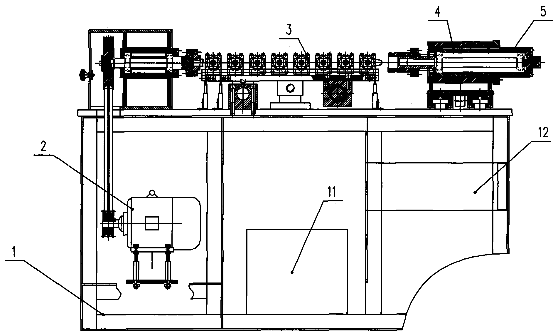
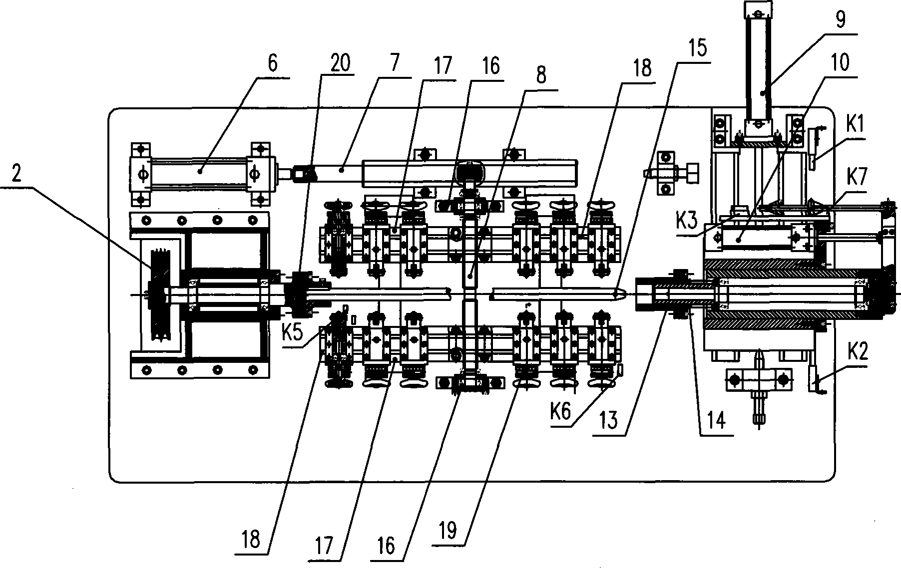
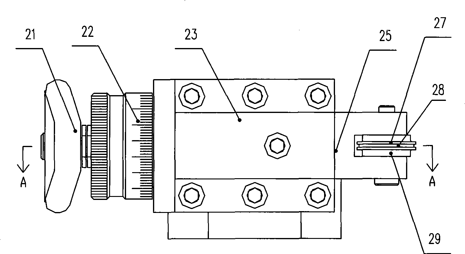
[0022] Attached below Figure 1-4 A detailed description will be made to the specific embodiment of the present invention.

[0023] Such as Figure 1-4 A metal cross-flow fan rolling riveting forming machine shown is composed of a frame 1 and a rolling riveting shaft rotating mechanism installed on the frame 1, a rolling riveting mechanism 3 and a fastening mechanism 4.

[0024] The rolling riveting shaft rotation mechanism is composed of a motor 2 and a rolling riveting shaft 15. The motor 2 is installed on the lower part of the frame 1. One end of the rolling riveting shaft 15 is fixed on the output end of the motor 2 and can rotate with it. The rolling riveting shaft 15 Install above the top surface of rack 1.

[0025] The rolling riveting mechanism 3 is composed of a feed control device, a screw mandrel 8 which is vertically arranged on the top surface of the frame 1 with the rolling riveting shaft 15, two hob rests 17 which are arranged in parallel with the rolling rive...


PUM


Abstract

The invention relates to processing equipment of a metal crossflow fan. A rolling-riveting shaping machine of the metal crossflow fan comprises a frame (1) and a rolling-riveting shaft rotating mechanism, a rolling-riveting mechanism (3) and a fastening mechanism (4) which are arranged on the frame (1). The rolling-riveting shaping machine of the metal crossflow fan has the advantages that: full-automation operation is employed, and an operator only needs to carry out operation on feeding and discharging; the processing efficiency is high; the coaxiality of each middle disc of the vane is very consistent, and the situation of radial jumping can not appear; moreover, the reject rate of processing is very low.

Description

technical field [0001] The invention relates to processing equipment for metal cross-flow fans. Background technique [0002] The metal cross-flow fan impeller is composed of a number of metal blades inserted into the grooves on the circumference of the middle plate, and the outer circumference of the middle plate is squeezed by rolling riveting forming machine, so that the middle plate and the blades are compressed and fixed. Existing fixed roll riveting forming equipment mainly includes a roll riveting shaft rotating mechanism and an extruded part propulsion device. When in use, the metal cross-flow fan is set on the rolling riveting shaft and fixed. The motor controls the rotation of the rolling riveting shaft to drive the metal cross-flow fan to rotate. The knife performs roll riveting on the next middle plate, and the feed distance determines the force of the middle plate, and the feed distance is controlled and adjusted by the operator with naked eyes. The defects of...

Claims


Application Information

Patent Timeline
IPC IPC(8): F04D29/30F04D29/62
Inventor 高炎康黄其全
Owner ZHEJIANG LANGDI GROUP
Why Eureka
Try Eureka