
Healthcare device for cold-hot compress

A technology of hot and cold compresses and refrigeration sheets, applied in the electrical field, can solve the problems of high cost of appliances, inconvenient use, unsuitable for daily home use, etc., and achieve the effect of being convenient to go out and portable and small in size

Inactive Publication Date: 2009-06-03
陈齐武
View PDF0 Cites 15 Cited by
  • Summary
  • Abstract
  • Description
  • Claims
  • Application Information

AI Technical Summary

Problems solved by technology

[0005] However, in the above-mentioned application scenarios, the preparation of various self-help auxiliary tools is cumbersome and has the disadvantage of being inconvenient to use
Professional appliances cost more and are not suitable for daily home use.

Method used


Image

  • Healthcare device for cold-hot compress
  • Healthcare device for cold-hot compress
  • Healthcare device for cold-hot compress

Examples


Embodiment 1

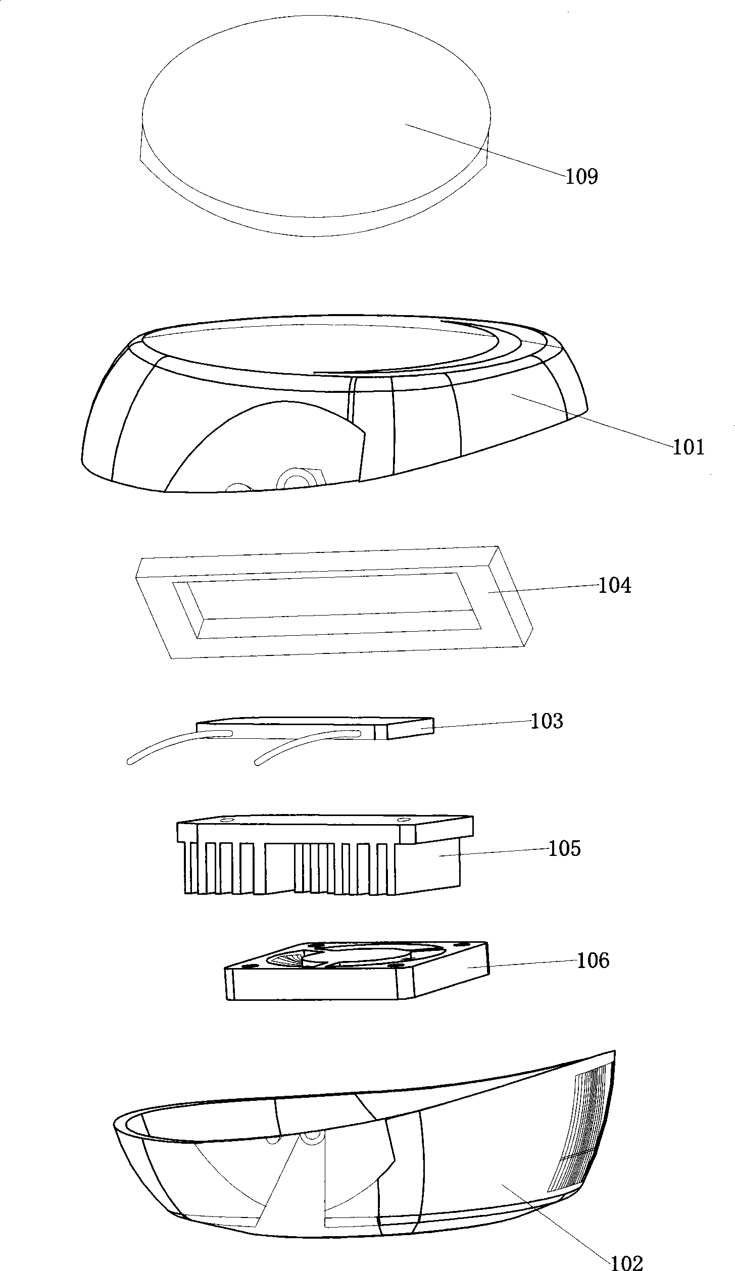
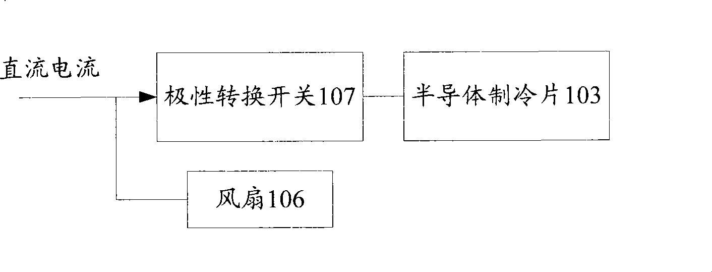
[0038] figure 1 A cold and hot compress device suitable for home use provided by this embodiment, figure 2 A schematic diagram of its circuit structure. see figure 1 , 2 The device mainly includes: an upper cover 101 , a polarity changeover switch 107 , a semiconductor cooling sheet 103 , a sponge rubber 104 , a heat sink 105 , a fan 106 , and a lower cover 102 .

[0039] Wherein, the upper cover 101 and the lower cover 102 are fixedly connected together to form the shell of the device, and the input end of the polarity changeover switch 107 is connected to a DC power supply. Wherein, the DC power supply can be a built-in power supply of the device, or an external power supply.

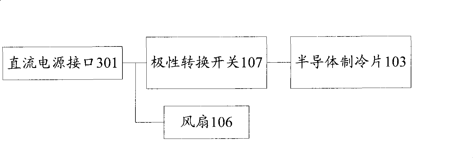
[0040] For example: see image 3 A DC power interface 301 may be provided on the casing of the device, and the input terminal of the polarity changeover switch 107 is electrically connected to the DC power interface 301 to be connected to an external DC power supply. For example, the user can a...

Embodiment 2

[0064] see Figure 7 As shown, the difference between the device of this embodiment and embodiment 1 is:

[0065] In this embodiment, in order to further improve the working stability of the device, further protect the semiconductor cooling chip 103, and prolong its service life, the polarity changeover switch 107 and the semiconductor cooling chip 103 are electrically connected through a voltage stabilizing circuit 701:

[0066] Specifically: the output end of the polarity changeover switch 107 is electrically connected to the input end of the voltage stabilizing circuit 701, the output end of the voltage stabilizing circuit 701 is electrically connected to the semiconductor cooling chip 103, and the current is processed by the voltage stabilizing circuit 701 and then input to the semiconductor cooling chip 103. The voltage stabilizing circuit 701 can alleviate the interference of voltage and current instability factors on the semiconductor cooling chip 103, can protect the s...


PUM


Abstract

The invention relates to the electricity field, and discloses a healthcare device for cold-hot compress. The healthcare device comprises an upper cover and a lower cover which are fixedly connected, space formed by the upper cover and the lower cover is internally provided with a semiconductor refrigeration piece, gelatin sponge, a radiating fin, a fan and a polarity-reversing switch; a DC power socket is arranged on the upper cover or the lower cover, the DC power socket is electrically connected with an input terminal of the polarity-reversing switch, and an output terminal of the polarity-reversing switch is respectively electrically connected with the semiconductor refrigeration piece and the fan; the semiconductor refrigeration piece is arranged in the center through hole of the gelatin sponge; aluminum heat conducting fin is fixed on the upside of the semiconductor refrigeration piece by radiating glue, and the aluminum heat conducting fin is embedded at an opening of the top surface of the upper cover; and the radiating fin is fixed on the underside of the semiconductor refrigeration piece by the radiating glue, the fan is fixed on the underside of the radiating fin, and an air hole is arranged on the lower cover. The healthcare device for cold-hot compress can be more conveniently used.

Description

technical field [0001] The invention relates to the electrical field, in particular to a cold and hot compress device. Background technique [0002] Along with the raising of people's living standard, need often need to carry out cold compress or hot compress to skin in daily life. for example: [0003] When the human body is bruised or has a fever, it is necessary to use ice packs or cold towels to apply on the skin for physical cooling, so as to relieve the condition and the pain of the patient. [0004] In addition, in the beauty industry, people, especially female friends, often need to use hot and cold towels or other professional appliances to apply cold or hot compresses to the skin, so as to increase blood circulation and help skin rejuvenation. [0005] However, in the above-mentioned application scenarios, the preparation of various self-help auxiliary tools is cumbersome and has the disadvantage of being inconvenient to use. And professional utensil cost is big...

Claims


Application Information

Patent Timeline
Patent Type & Authority Applications(China)
IPC IPC(8): A61F7/00
Inventor 李耀亮陈齐武
Owner 陈齐武
Learn More