
Receptacle with crosstalk optimizing contact array

A technology of contact arrays and arrays, which is applied to the parts of connecting devices, coupling devices, two-part connecting devices, etc.

Active Publication Date: 2009-05-20
TE CONNECTIVITY CORP
View PDF0 Cites 9 Cited by
  • Summary
  • Abstract
  • Description
  • Claims
  • Application Information

AI Technical Summary

Problems solved by technology

The problem is that as frequency increases, the system experiences more signal attenuation due to EM signal coupling, return loss, and mismatched impedance

Method used


Image

  • Receptacle with crosstalk optimizing contact array
  • Receptacle with crosstalk optimizing contact array
  • Receptacle with crosstalk optimizing contact array

Examples


Embodiment Construction

[0016] The foregoing summary, as well as the following detailed description of specific embodiments of the invention, will be better understood when read in conjunction with the accompanying drawings. It should be understood that the invention is not limited to the arrangements and instrumentalities shown in the drawings.

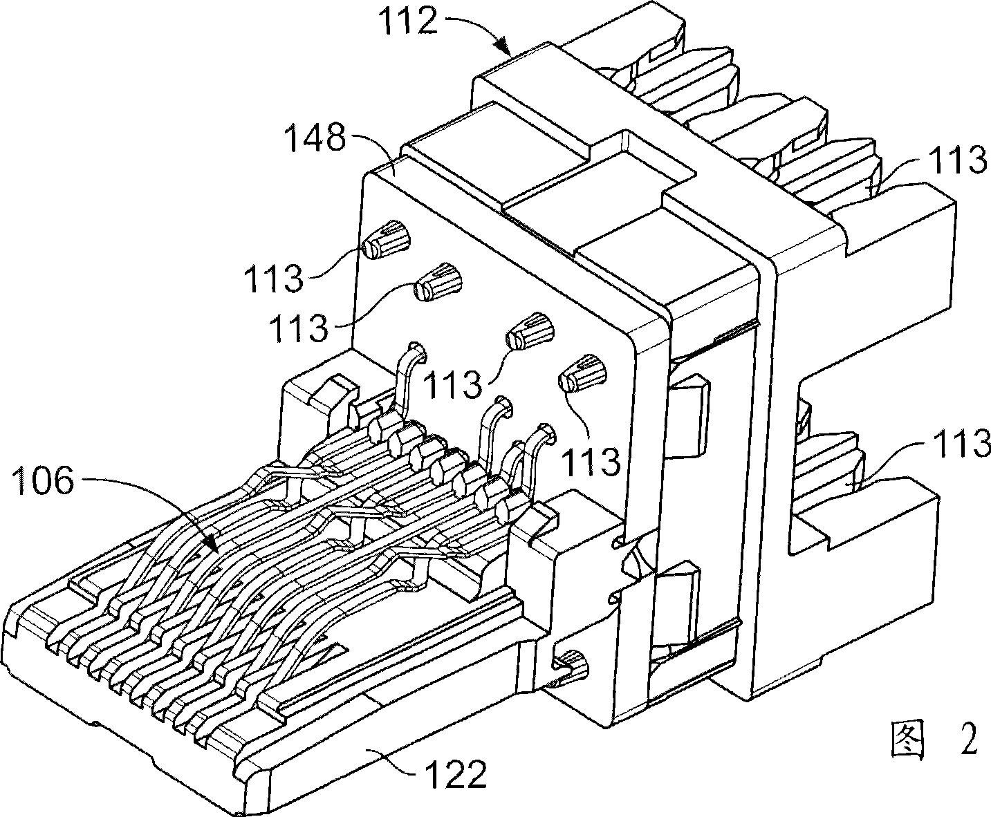
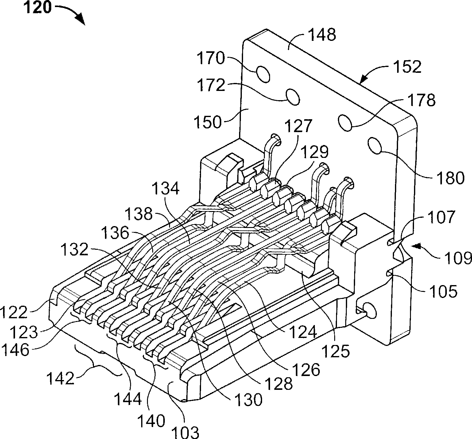
[0017] FIG. 1 shows a socket assembly 100 . The receptacle assembly 100 has a front end 102 and a rear end 114 . Housing 108 partially surrounds contact array 106 in cavity 110 . In the example of FIG. 1 , cavity 110 receives an RJ-45 plug (not shown) inserted through front end 102 . The RJ-45 plug has contacts in electrical contact with contact array 106 . A circuit board 148 ( FIG. 2 ) is mounted within the housing 108 proximate to the rear end 104 of the housing. The front end 116 of the wire connector housing 112 mates with the housing rear end 104 . The wire connector housing 112 receives wires from a cable (not shown) passing through the rear end...


PUM


Abstract

A receptacle assembly comprises a housing having front and rear ends. The front end receives a plug and the rear end accepts wire termination contacts. A circuit board has a plurality of contact holes and is held within the housing. A plurality of array contacts is arranged in a contact array within the housing. Each of the plurality of array contacts comprises a main section and a contact tail. The main section runs generally perpendicular to the circuit board. The contact tail has a first bend forming a first tail sub-section extending parallel to the circuit board and a second bend forminga second tail sub-section extending perpendicular to the circuit board. The second tail sub-section of each of the plurality of array contacts is received by one of the plurality of contact holes in the circuit board.

Description

technical field [0001] The present invention relates generally to an electrical connector, and more particularly to a modular jack or receptacle having an array arrangement for reducing crosstalk. Background technique [0002] Various electronic systems include connector assemblies having electrical conductors arranged in differential pairs, such as those used in the telecommunications industry for transmitting signals. One wire in a differential pair carries a positive signal, and the other wire carries a negative signal of the same absolute value but at opposite polarity. [0003] An RJ-45 electrical connector with a plug and outlet jack is an example of a connector used to carry electrical signals in a differential pair. Plugs have a high level of noise due to the arrangement of wires determined by industry standards. [0004] Multiple differential pairs are positioned in close proximity to each other in the connector and create undesirable electromagnetic (EM) signal c...

Claims


Application Information

Patent Timeline
Patent Type & Authority Applications(China)
IPC IPC(8): H01R24/04H01R12/55H01R13/6474H01R13/719H01R24/58
CPCH01R23/025H01R24/64Y10S439/941H01R23/005H01R13/6477H01R13/6469H01R12/71H01R12/55
Inventor 琳达·E·希尔兹保罗·J·佩普
Owner TE CONNECTIVITY CORP
Learn More