
Large slanting view angle machine-carried SAR beam bunching mode imaging method based on non-uniform sampling

A non-uniform sampling and imaging method technology, applied in the direction of radio wave reflection/re-radiation, using re-radiation, measuring devices, etc., can solve the problems of non-existence, large amount of calculation, etc., and achieve large squint angle, small amount of calculation, Effects that are easy to process in real time

Inactive Publication Date: 2009-05-13
BEIHANG UNIV +1
View PDF0 Cites 65 Cited by
  • Summary
  • Abstract
  • Description
  • Claims
  • Application Information

AI Technical Summary

Problems solved by technology

The above method is mainly aimed at the high squint strip mode, and has the disadvantage of large amount of calculation
For the spotlight mode with large oblique angle of view, the commonly used method is Polar Format Algorithm (PFA). This method requires the radar system to have the Dechirp demodulation function of scene center tracking, but many actual radar systems do not have this function.

Method used


Image

  • Large slanting view angle machine-carried SAR beam bunching mode imaging method based on non-uniform sampling
  • Large slanting view angle machine-carried SAR beam bunching mode imaging method based on non-uniform sampling
  • Large slanting view angle machine-carried SAR beam bunching mode imaging method based on non-uniform sampling

Examples


Embodiment Construction

[0017] The present invention will be described in detail below in conjunction with the accompanying drawings and specific embodiments.

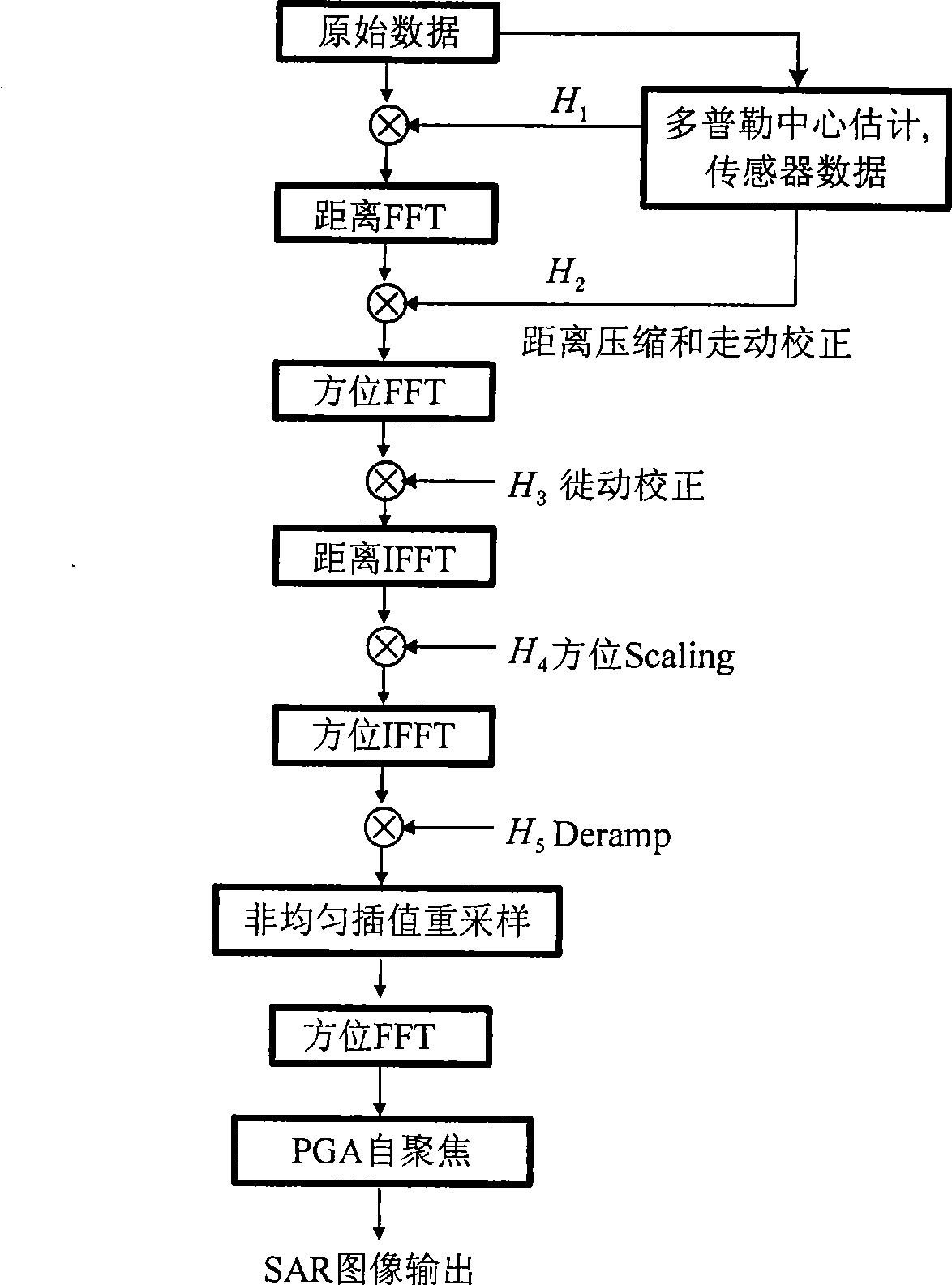
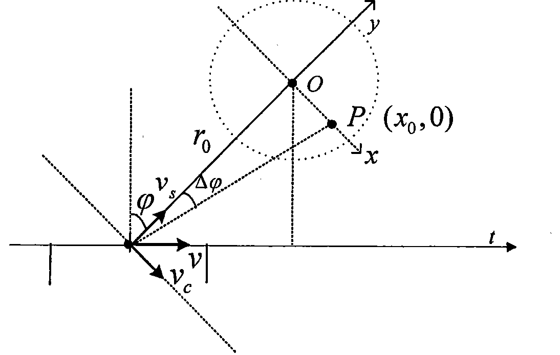
[0018] The processing flow of the large oblique viewing angle airborne SAR spotlight mode imaging method of the present invention is as follows figure 1 As shown, firstly, the airborne SAR data acquisition model under the condition of large oblique angle of view can be equivalent to the side-looking data acquisition model with additional motion compensation, and the corresponding spotlight SAR irradiation geometry is as follows: figure 2 shown. Assume that the radar uses chirp waves, and the modulation frequency is k r , the working wavelength is λ, the pulse repetition frequency is PRF, the flight speed of the carrier aircraft is v, τ represents the fast time in the distance direction, t represents the slow time in the azimuth direction, and f r Indicates the range frequency, f a Indicates the azimuth frequency, at time t=0, the distance...


PUM


Abstract

The invention discloses an imaging method by a large squint angle airborne SAR spotlight mode based on non-uniform sampling. Based on an analysis of azimuth signals characteristics of targets at different azimuths on the same range gate under the condition of a large squint angle, the method enlarges the azimuth imaging range output by effective focuses by a non-uniform interpolation resampling processing method. In the method, a data acquisition model under the large squint angle is equated with a right side looking data acquisition model of increment motion compensation. The method comprises the following steps: firstly, performing cubic phase compensation in an original data field, then performing range walk correction on a time domain and range migration correction on a 2D frequency domain, completing azimuth compression by the non-uniform interpolation resampling method, and finally, completing autofocus processing by a phase gradient autofocus algorithm. Compared with the prior art, the method can help process a larger squint angle, and has the advantages of small calculation amount and easy real-time processing. The method can be applicable to the conventional radar systems without a function of tracing Dechirp demodulation by a scene center.

Description

technical field [0001] The invention belongs to the field of synthetic aperture radar imaging processing, and relates to a beamforming mode imaging method of airborne synthetic aperture radar with large oblique viewing angle, which is suitable for airborne fire control radar, millimeter wave auxiliary landing radar and missile-borne SAR system. Background technique [0002] When SAR is used for reconnaissance and surveying and mapping, it generally adopts the front side view, and the beam points to the front side of the flight direction. However, in many cases, it is necessary to point the beam at a large angle. For example, fighter jets and bombers need to observe the situation ahead. At this time, the radar’s The front was regarded as accurate in the past. Even if the phased array system is adopted, the SAR imaging of the ground can only deviate from the forward limited angle (for example, up to 60 degrees), and this kind of forward squint observation has more practical adv...

Claims


Application Information

Patent Timeline
IPC IPC(8): G01S13/90G01S7/02
Inventor 孙进平刘振华洪文王文光
Owner BEIHANG UNIV
Learn More