Eureka AIR delivers breakthrough ideas for toughest innovation challenges, trusted by R&D personnel around the world.

Wide-band annular dual polarized radiating element and linear array antenna

A radiating unit and wide-band technology, which is applied to the combination of antenna units with different polarization directions, antenna arrays and antennas powered separately, can solve the problems of reducing antenna gain, reducing network communication quality, and large orthographic projection area, etc., to achieve Good electrical performance and radiation performance, high cross-polarization discrimination rate, high isolation effect

Active Publication Date: 2009-05-06
COMBA TELECOM TECH (GUANGZHOU) CO LTD +1
View PDF6 Cites 69 Cited by
  • Summary
  • Abstract
  • Description
  • Claims
  • Application Information

AI Technical Summary

Problems solved by technology

[0004] The base station antenna is the key component of the outdoor coverage of the mobile communication system. At present, the polarization diversity form of the base station antenna is mainly dual-polarization, and the dual-polarization antenna is mainly ±45° dual-polarization, and the ±45° base station antenna is also The mainstream products are antenna series with a beamwidth of 65° in the horizontal plane. The performance of this series of products directly affects the coverage and polarization diversity gain of the mobile communication system, thus affecting the operation quality of the entire network.
[0005] In the prior art, the ±45° dual-polarized base station antenna composed of a conventional symmetrical oscillator radiating element or a microstrip radiating element has a high cross-polarization discrimination rate of less than 10% of the relative operating frequency band, which affects the +45° antenna and the -45° antenna. °Antenna correlation, which affects the diversity effect of the antenna when it works in a broadband; Increase the gain of the antenna, increase the number of handovers in the border area, and reduce the communication quality of the network; the working frequency band width of the general symmetrical vibrator is about 13%, and for the antenna of the microstrip radiating unit, the frequency band width is narrower, under 10%
[0008] However, the radiating units in the above-mentioned patents have relatively large orthographic projection areas and complex structures, which have at least three disadvantages:
[0009] 1. The high-frequency oscillator in the middle of the two low-frequency oscillators is coupled by the low-frequency oscillator, which deteriorates the radiation performance of the high-frequency band;
[0010] 2. If the communication system puts forward higher requirements for the control of the vertical grating lobe of the multi-frequency electric-tunable base station antenna, the distance between the radiating units will be reduced, between the low-frequency oscillator and the low-frequency oscillator, and between the low-frequency oscillator and the high-frequency oscillator The mutual coupling of the antenna becomes more serious, even unacceptable, which greatly reduces the circuit characteristics and radiation characteristics of the antenna;
[0011] 3. In multi-frequency shared base station antennas, there are often some low-frequency oscillators that are not inlaid with high-frequency oscillators, and the impedance characteristics of low-frequency oscillators that are embedded with high-frequency oscillators and those that are not embedded with high-frequency oscillators vary greatly
[0012] Therefore, although the design of the radiating unit is physically intuitive, its technical evolution process is complicated, especially the relationship between its size and electrical performance (technical parameters) needs to be properly handled

Method used


Image

  • Wide-band annular dual polarized radiating element and linear array antenna
  • Wide-band annular dual polarized radiating element and linear array antenna
  • Wide-band annular dual polarized radiating element and linear array antenna

Examples


Embodiment Construction

[0040] Below in conjunction with accompanying drawing description and embodiment, the present invention will be further described:

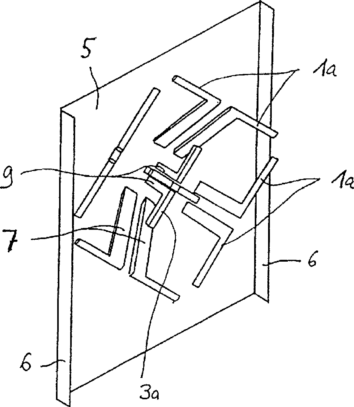
[0041] see image 3 and Figure 4 , in the first preferred embodiment of the present invention, the broadband annular dual-polarized radiation unit 9 includes two pairs of four symmetrical oscillators 1, 2, 3, 4, and includes corresponding symmetrical oscillators 1, 2, 3, 4 Four equalizers 5 a , 5 b , 5 c , and 5 d are arranged in numbers, and the four equalizers 5 a , 5 b , 5 c , and 5 d are arranged on an annular base 6 .

[0042] Each symmetrical vibrator 1, 2, 3, 4 is set on the corresponding balancer 5a, 5b, 5c, 5d, and each balancer 5a, 5b, 5c, 5d is supported by the annular base 6, and the corresponding walking The wire slot, on which the electrical circuit is laid, is electrically connected with the corresponding symmetrical vibrator 1, 2, 3, 4 for balanced feeding. The balancers 5a, 5b, 5c, 5d simultaneously play the role of balancing...


PUM


Abstract

The invention discloses a broadband annular dual-polarization radiation unit and a linear array antenna applying the radiation unit. The radiation unit is used to be installed on a metal reflecting board to form a communication antenna and comprises the following parts: two pairs of orthogonal polarization dipoles used for transmitting or receiving communication signals, and balancers corresponding to the dipoles for performing balanced feeding to each dipole; each dipole comprises two unit arms which are symmetrically and fixedly arranged on the balancer, and show symmetrical lines with the balancers. One end of each unit arm is fixedly arranged on the balancer, and the other end of each unit arm is provided with a vertically downward loaded line and evenly provided with tuning branches with the size of the cross section being different from that of the cross section of the unit arm. The broadband annular dual-polarization radiation unit has the advantages of wide bandwidth, high efficiency, high isolation, high cross polarization discrimination, and small discreteness of the beam width with the variation of frequency, and the like, can be used as a separate antenna, and more used as an array group unit of the array antenna.

Description

【Technical field】 [0001] The invention relates to the field of mobile communication antennas, in particular to a miniaturized wide-band annular dual-polarization radiation unit, and at the same time, a linear array antenna using the radiation unit. 【Background technique】 [0002] With the development of the communication industry, 2G and 3G networks will coexist for a long time. In order to meet the coverage requirements of different communication networks, the mobile communication system has higher and higher requirements for antennas. Antenna needs are more urgent. [0003] In order to meet the network optimization of different communication systems, the accuracy requirements for the horizontal plane beam width of the antenna are getting higher and higher, and the vertical plane pattern also needs to generally adopt the lobe shaping technology to realize the suppression of the upper side lobe and the lower side null point padding for more reliable data communication quali...

Claims


Application Information

Patent Timeline
Patent Type & Authority Applications(China)
IPC IPC(8): H01Q21/24H01Q21/26H01Q21/29H01Q5/00H01Q5/42H01Q5/48
CPCH01Q9/26H01Q21/08H01Q5/0075H01Q21/26H01Q5/0086H01Q5/42H01Q5/48
Inventor 卜斌龙刘培涛孙善球范颂东苏小兵
Owner COMBA TELECOM TECH (GUANGZHOU) CO LTD
Why Eureka
Eureka Blog
Learn More