
Nonreciprocal circuit element

A technology of circuit components and resistors, which is applied in the field of non-reciprocal circuit components, can solve the problems of inappropriate miniaturization and thinning, and achieve the effects of easy and attenuation, adjustable attenuation, and reliable out-of-band attenuation

Inactive Publication Date: 2009-04-01
TDK CORPARATION
View PDF2 Cites 0 Cited by
  • Summary
  • Abstract
  • Description
  • Claims
  • Application Information

AI Technical Summary

Problems solved by technology

[0011] However, the use of the nonreciprocal circuit element described in Patent Document 2 is not suitable for miniaturization and thinning because it is necessary to insert a complex circuit in which capacitors and LC parallel circuits are connected in series between the common node of the central conductor and the ground.

Method used


Image

  • Nonreciprocal circuit element
  • Nonreciprocal circuit element
  • Nonreciprocal circuit element

Examples


Embodiment Construction

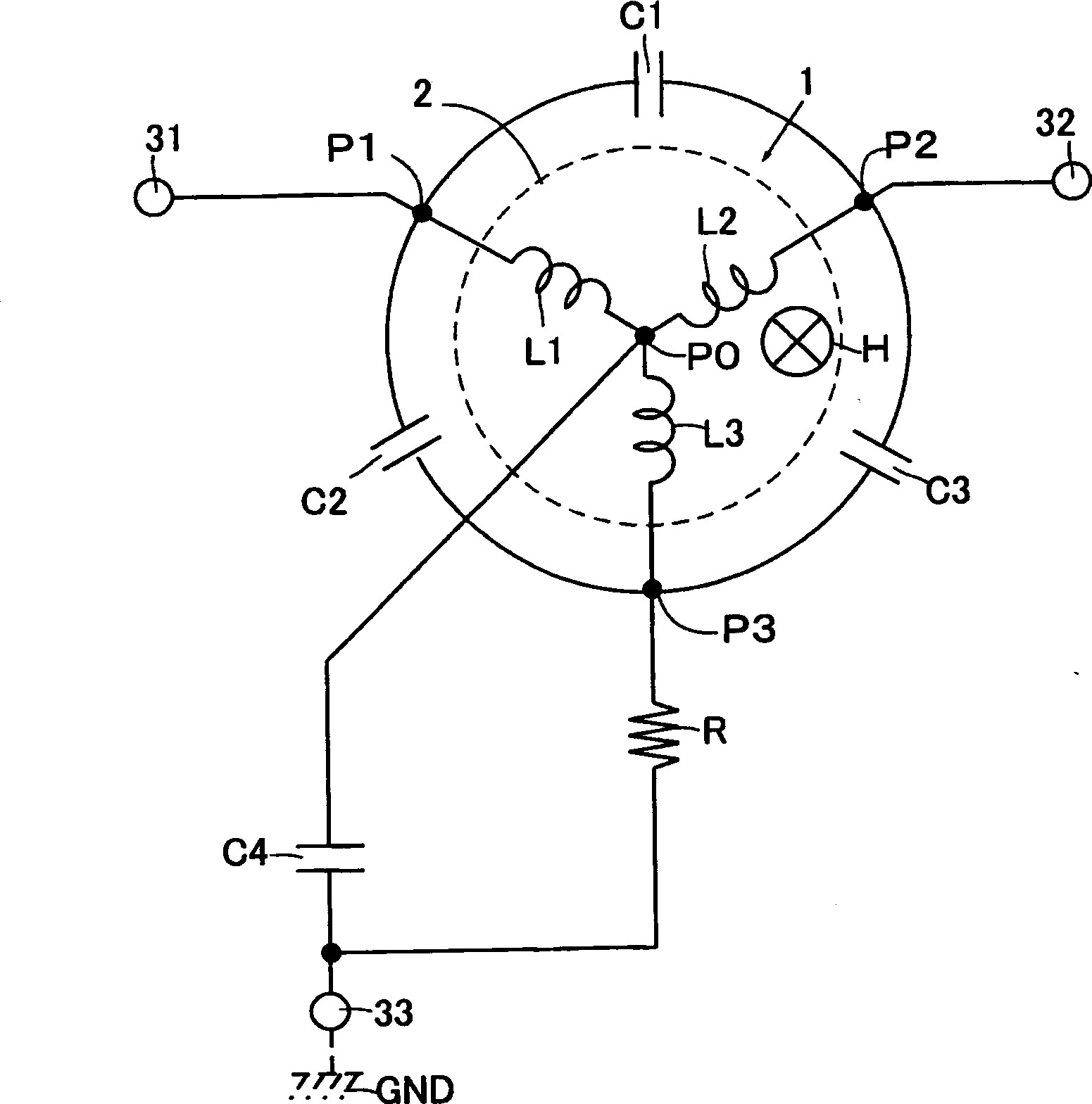
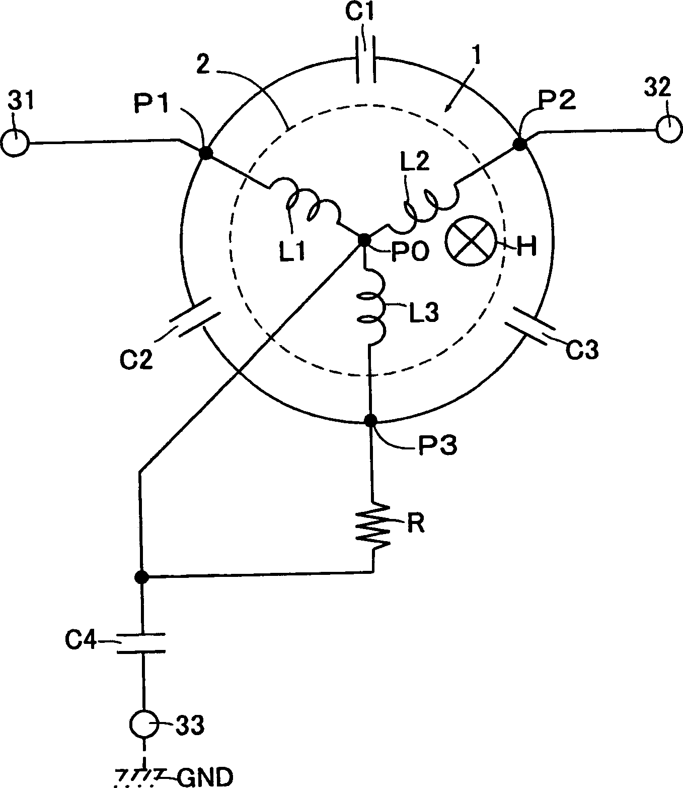
[0064] figure 1 It is a circuit diagram of the nonreciprocal circuit element involved in the present invention. The illustrated non-reciprocal circuit element includes a magnetic rotor 1 , first to fourth capacitors C1 to C4 and a terminal resistor R.

[0065] The magnetic rotor 1 includes a ferrite 2 and first to third center conductors L1 to L3. The ferrite 2 can be formed in any shape such as a disc shape, a square plate shape, or the like.

[0066] The first to third central conductors L1-L3 are connected to the ferrite 2 through the common node P0 with one end at the common potential. The first to third central conductors L1-L3 are made of metal materials such as Cu with good electrical conductivity and high-frequency characteristics. In addition to Cu plates, conductive paste with Cu or Ag as the main component can also be used for coating and sintering. and other well-known structures in the past. These first to third central conductors L1 to L3 are insulated from e...


PUM


Abstract

The present invention relates to an inreversible circuit element which is suitable for miniaturization / thinning and can adjust the attenuation amount, the insertion loss, the working frequency, the 10dB frequency band rate and the required working magnetic field easily and reliably, and furthermore the inreversible circuit element can realiably insure the attenuation outside the frequency band. One end of each of a first central conductor to a third central conductor L1 to L3 is connected on a shared potential P0 to combine with a ferrite 2 for forming a magnetic rotor 1. A first capacitor C1 is connected between the other end P1 of the first central conductor L1 and the other end P2 of a second central conductor L2. A second capacitor C2 is connected between the other end P1 of the first central conductor L1 and the other end P3 of the third central conductor L3. A third capacitor C3 is connected between the other end P2 of the second central conductor and the other end P3 of the third central conductor L3. A fourth capacitor C4 is connected between a sharing potential P0 and an earthing terminal 33. A terminal resistor R is connected between the other end P3 of the third central conductor L3 and one capacitor electrode of the fourth capacitor C4.

Description

technical field [0001] The present invention relates to a non-reciprocal circuit element used as an isolator. Background technique [0002] Such a nonreciprocal circuit element is incorporated in, for example, wireless equipment used in the microwave band, specifically mobile wireless equipment such as mobile phones, in order to separate the two systems functionally in the following circuit configuration so that there is no transmission When the signal affects the receiving system or the received signal affects the transmitting system, the above-mentioned circuit structure is such that the transmitting signal output from the transmitting system is supplied to the antenna, and the receiving signal received by the antenna is guided to the The circuit structure of the receiving system. [0003] This type of nonreciprocal circuit element applies a DC magnetic field from a magnet to a magnetic rotor in which a central conductor is combined with ferrite. A conventionally known t...

Claims


Application Information

Patent Timeline
Patent Type & Authority Applications(China)
IPC IPC(8): H01P1/383H01P1/36H01P1/32
Inventor 大波多秀典松丸宜纪笠原龙一
Owner TDK CORPARATION
Learn More