Internal-combustion engine with decompressor

A technology of decompression device and internal combustion engine, which is applied to valve devices, mechanical equipment, engine components, etc., to achieve the effect of improving switching accuracy and suppressing sway rotation and vibration

Active Publication Date: 2011-10-12
HONDA MOTOR CO LTD
View PDF5 Cites 0 Cited by
  • Summary
  • Abstract
  • Description
  • Claims
  • Application Information

AI Technical Summary

Problems solved by technology

[0005] In addition, when the centrifugal load and decompression cam are installed on the camshaft, the camshaft itself is enlarged in the radial direction, and it is necessary to secure a space for the centrifugal load to swing, so the cylinder head is enlarged in the radial direction of the camshaft.

Method used


Image

  • Internal-combustion engine with decompressor
  • Internal-combustion engine with decompressor
  • Internal-combustion engine with decompressor

Examples


Embodiment Construction

[0046] Below, refer to Figure 1 to Figure 6 Examples of the present invention will be described.

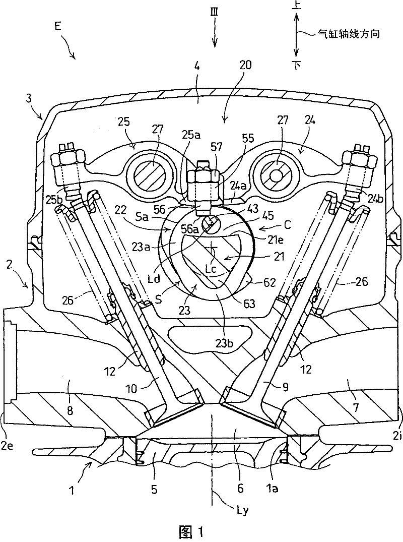
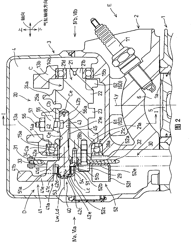
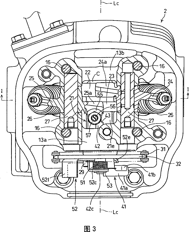
[0047] refer to figure 1 , figure 2, the internal combustion engine E to which the present invention is applied is a single-cylinder reciprocating 4-stroke internal combustion engine mounted on a motorcycle as a vehicle. The air-cooled internal combustion engine E is equipped with an engine main body composed of a cylinder 1 forming a cylinder bore 1a in which a piston 5 can reciprocate and fit, a cylinder head 2 connected to the upper end of the cylinder 1, and a cylinder head 2 connected to the upper end of the cylinder head 2. The cylinder head cover 3 is connected to the lower end of the cylinder 1 and includes a crankcase (not shown) that rotatably supports a crankshaft (hereinafter referred to as "crankshaft"). A valve chamber 4 is formed by the cylinder head 2 and the cylinder head cover 3 , and the valve chamber accommodates an overhead cam type valve device 20 mount...


PUM


Abstract

The invention provides an internal-combustion engine (E) with a reliever, which reduces the rotating imbalance of a camshaft through the reliever and simultaneously improves the switching accuracy of an engine valve through a valve cam, comprising a centrifugal load(41) which can be supported on the camshaft of an valve device(20) in a swinging way, a reliever(D) with a relief cam(43),which can be driven by the swinging centrifugal load(41).When an engine is started to cause the centrifugal load(41) to occupy the low-speed side position, and when the relief cam(43)occupies the pressure strokewhich should reduce the compression pressure in the combustion space, the decompression position of the engine valve is opened; and after an engine is started to cause the centrifugal load(41) to occupy the high-speed side position, the decompression lifting position which does not open the engine valve is occupied. A balancing load (60) is arranged on the camshaft, which is used to reduce the rotating imbalance of the camshaft caused by the centrifugal load(41)occupying the high-speed side position. Wherein, the balancing load (60) comprises a plurality of load parts(61,62,52e) which are isolated with each other in the axial direction.

Description

technical field [0001] The present invention relates to an internal combustion engine provided with a decompression device which lowers the compression pressure at startup and facilitates startup. Background technique [0002] A known decompression device for an internal combustion engine has: a centrifugal load swingably supported on a camshaft of a valve device for opening and closing an intake valve and an exhaust valve, and a decompression cam driven by the centrifugal load swinging under the action of centrifugal force, The engine valve switched by the decompression cam is driven to open by the decompression cam during the compression stroke, thereby reducing the compression pressure in the combustion space, thereby reducing the load on the starting device. (For example: refer to Patent Document 1) [0003] Patent Document 1: JP-A-2004-360538 [0004] However, since the centrifugal load of the decompression device is arranged so as to have a center of gravity at an ec...

Claims


Application Information

Patent Timeline
Patent Type & Authority Patents(China)
IPC IPC(8): F01L13/08
Inventor 久保田良河野直树佐藤岳久
Owner HONDA MOTOR CO LTD
Why Eureka
Try Eureka