Endoscopic imaging device

A camera device and endoscope technology, applied in the direction of endoscopes, applications, telescopes, etc., can solve problems such as the diameter of the end of the endoscope becomes larger

Inactive Publication Date: 2016-11-09
FUJIFILM CORP
View PDF3 Cites 0 Cited by
  • Summary
  • Abstract
  • Description
  • Claims
  • Application Information

AI Technical Summary

Problems solved by technology

Therefore, the diameter of the distal end of the endoscope becomes larger

Method used


Image

  • Endoscopic imaging device
  • Endoscopic imaging device
  • Endoscopic imaging device

Examples


Embodiment Construction

[0042] Hereinafter, preferred embodiments of the present invention will be described in detail with reference to the drawings.

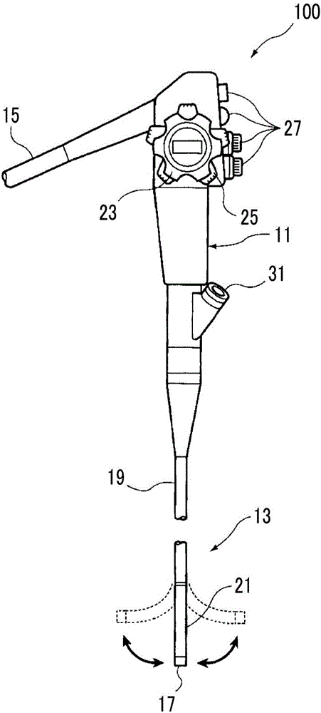
[0043] figure 1 It is an overall configuration diagram of an endoscope to which an imaging device for an endoscope to which the present invention is applied.

[0044] The endoscope 100 shown in this figure represents a known flexible endoscope, and includes a main body operating part 11 and an endoscope insertion part 13 provided continuously to the main body operating part 11 and inserted into a body cavity.

[0045] The general-purpose cord 15 is continuously provided on the main body operation part 11, and the end of the universal cord 15 is connected to a light source device for supplying illumination light to the endoscope 100 through a connector not shown, and to perform imaging of an image obtained from the endoscope 100. Processor devices for processing, etc. are connected. In addition, the connector of the universal cord 15 has a different...


PUM


Abstract

Provided is an endoscopic imaging device the size of which is reduced in a direction along an optical axis of an objective optical system and which can contribute to the size reduction of an imaging unit of an endoscope. An imaging device (60) disposed on a distal part (17) of an endoscope includes: a lens barrel (62) that holds an objective optical system (62a) which captures image light of a site to be observed and images the same; a right-angle prism (64) that bends, at a right angle, the direction of the light path of the image light that has passed through the objective optical system (62a); an imaging element (70) an imaging face (70a) of which is disposed along a face orthogonal to the direction of the light path bent by the right-angle prism (64); and a board (68) on which the imaging element (70) is mounted. The board (68) has a distal side region that extends distal to an imaging element mounting region on which the imaging element (70) is mounted, and an electronic component of a drive circuit (76) necessary to drive the imaging element (70) is mounted on the distal side region.

Description

technical field [0001] The present invention relates to an imaging device for an endoscope, and more particularly to an imaging unit of an endoscope that is mounted on the distal end of an endoscope insertion unit of a flexible scope, etc. An endoscope imaging device for reducing the size of an imaging unit of a scope. Background technique [0002] The imaging device for an endoscope is mounted on the distal end of an elongated insertion portion of an endoscope inserted into a body cavity (hereinafter, the insertion portion and the distal end of the endoscope are referred to as an endoscope insertion portion and an endoscope). Terminal part) and a device that takes images of the inside of the body cavity. This imaging device for endoscope has an objective optical system for forming an image light from an observation part of the endoscope, and a CCD (Charge Coupled Device) type image sensor or CMOS for converting the optical image formed by the objective optical system into ...

Claims


Application Information

Patent Timeline
Patent Type & Authority Applications(China)
IPC IPC(8): A61B1/04G02B23/24
CPCA61B1/00096G02B23/2476A61B1/05G02B23/2423G02B23/2484H04N23/555H04N23/56H04N23/55
Inventor 矢野孝
Owner FUJIFILM CORP
Why Eureka
Try Eureka