
End milling tool

A technology of end mills and tool holders, applied in the field of end mills, can solve problems such as high cost and environmental pollution, and achieve the effects of reducing processing costs, preventing environmental pollution, and inhibiting chip clogging

Inactive Publication Date: 2009-03-25
OSG
View PDF4 Cites 11 Cited by
  • Summary
  • Abstract
  • Description
  • Claims
  • Application Information

AI Technical Summary

Problems solved by technology

[0008] However, since cutting fluids generally contain harmful substances such as chlorine or phosphorus, there is a problem that environmental pollution may be induced when cutting fluids are used.
As a result, it is necessary to completely recover the cutting fluid, and the cost increases accordingly. In recent years, it is desired to develop a technology that can suppress the use of cutting fluid

Method used


Image

  • End milling tool
  • End milling tool
  • End milling tool

Examples


Embodiment Construction

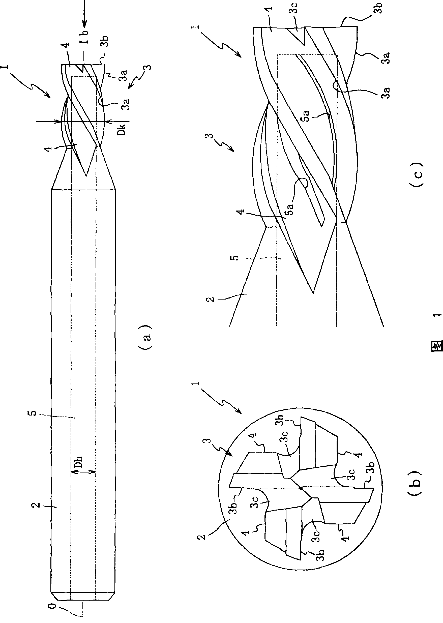
[0043] Hereinafter, preferred embodiments of the present invention will be described with reference to the drawings. First, an end mill 1 according to an embodiment of the present invention will be described with reference to FIG. 1 . Fig. 1 (a) is the front view of end mill 1, Fig. 1 (b) is the side view of end mill 1 observed from the direction of arrow 1b of Fig. 1 (a), Fig. 1 (c) is the main body part 3 Zoom in on the partial enlarged view of the obtained end mill 1.

[0044] The end mill 1 is a tool for cutting a workpiece (not shown) using a rotational force transmitted from a processing machine (not shown), and as shown in FIG. The cemented carbide obtained by pressing and sintering constitutes an integral square end mill, which mainly includes a handle 2 and a main body 3 connected to the handle 2 . However, the end mill 1 is not limited to cemented carbide, and may be made of high-speed tool steel.

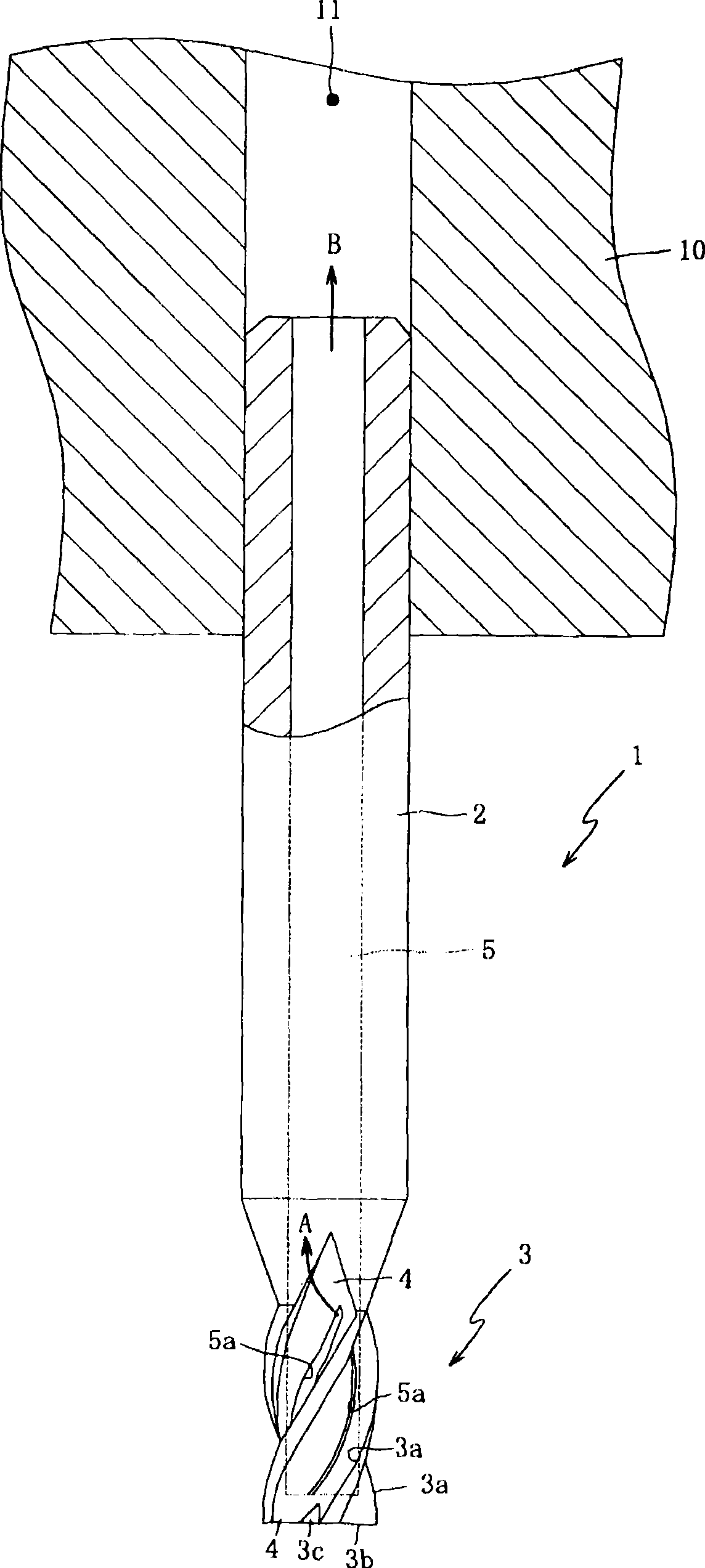
[0045] Knife handle 2 is via knife rest 10 (referring to figure ...


PUM


Abstract

An end mill that realizes prevention of environmental pollution. End mill (1) has aperture (5a) resulting from opening forming along helical flute (4). The aperture (5a) is so structured as to communicate via air suction channel (5) with an opening of the rear end face of shank (2). Accordingly, by air suction through the air suction channel (5), chips generated at cutting processing can be forcibly suctioned from the aperture (5a), and the suctioned chips can be discharged outside from the opening of the rear end face of shank (2). As a result, as compared with conventional products, the use of cutting liquid for eliminating of chips can be suppressed (or rendered unnecessary) to thereby attain prevention of environmental pollution.

Description

technical field [0001] The present invention relates to an end mill, and more particularly to an end mill capable of preventing environmental pollution. Background technique [0002] In general, when cutting with an end mill, it is important to supply cutting fluid to remove chips in order to prolong tool life and ensure machining accuracy. [0003] As a method of supplying cutting fluid, the external oil supply method is generally used to supply the cutting fluid from the outside to the cutting edge. However, this method has the problem that the cutting fluid is scattered due to centrifugal force during high-speed rotation and cannot be sufficiently supplied to the cutting edge. . Therefore, various technologies related to an internal oil supply system have been proposed in the past, which supply cutting fluid from an oil hole penetrating the inside of the end mill and have a better oil supply effect than the external oil supply system. [0004] Patent Document 1: JP-A-5-...

Claims


Application Information

Patent Timeline
Patent Type & Authority Applications(China)
IPC IPC(8): B23C5/10B23C5/28
CPCB23C5/28B23C5/10B23C2230/08Y10T407/1948Y10T409/304088
Inventor 菅野浩人大桥诚司
Owner OSG
Learn More