Pin Tumbler Lock

a technology of pin tumbler and lock, which is applied in the direction of cylinder locks, building locks, construction, etc., can solve the problems of not having a solution to prevent lock picking, and achieve the effect of preventing lock picking

Inactive Publication Date: 2008-06-05
JANES LOCK HK
View PDF12 Cites 9 Cited by
  • Summary
  • Abstract
  • Description
  • Claims
  • Application Information

AI Technical Summary

Benefits of technology

[0010]When the pins are mobilized by a bump key, the magnetized pins remain attracted to the corresponding magnetic permeable pin such that no open space between the first and the second pins is formed at the interface surface between the lock members to release the lock. The lock therefore prevents against lock picking by using bump keys.

Problems solved by technology

There is no solution yet to prevent lock picking using bump key.

Method used


Image

  • Pin Tumbler Lock
  • Pin Tumbler Lock
  • Pin Tumbler Lock

Examples


Embodiment Construction

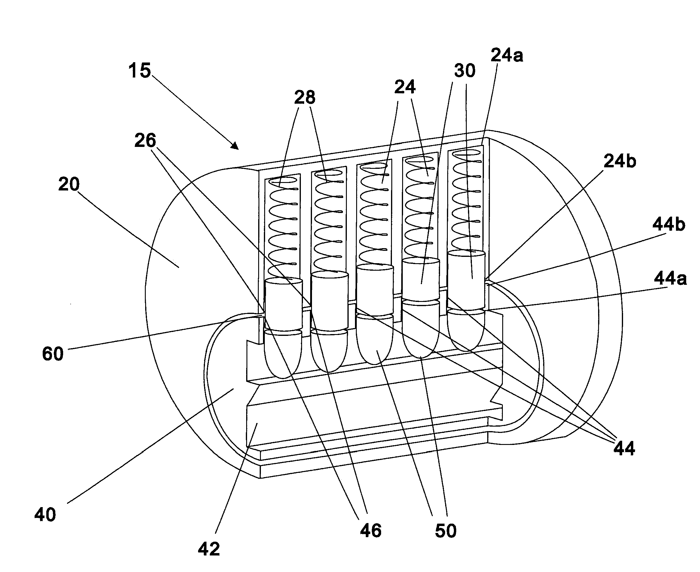
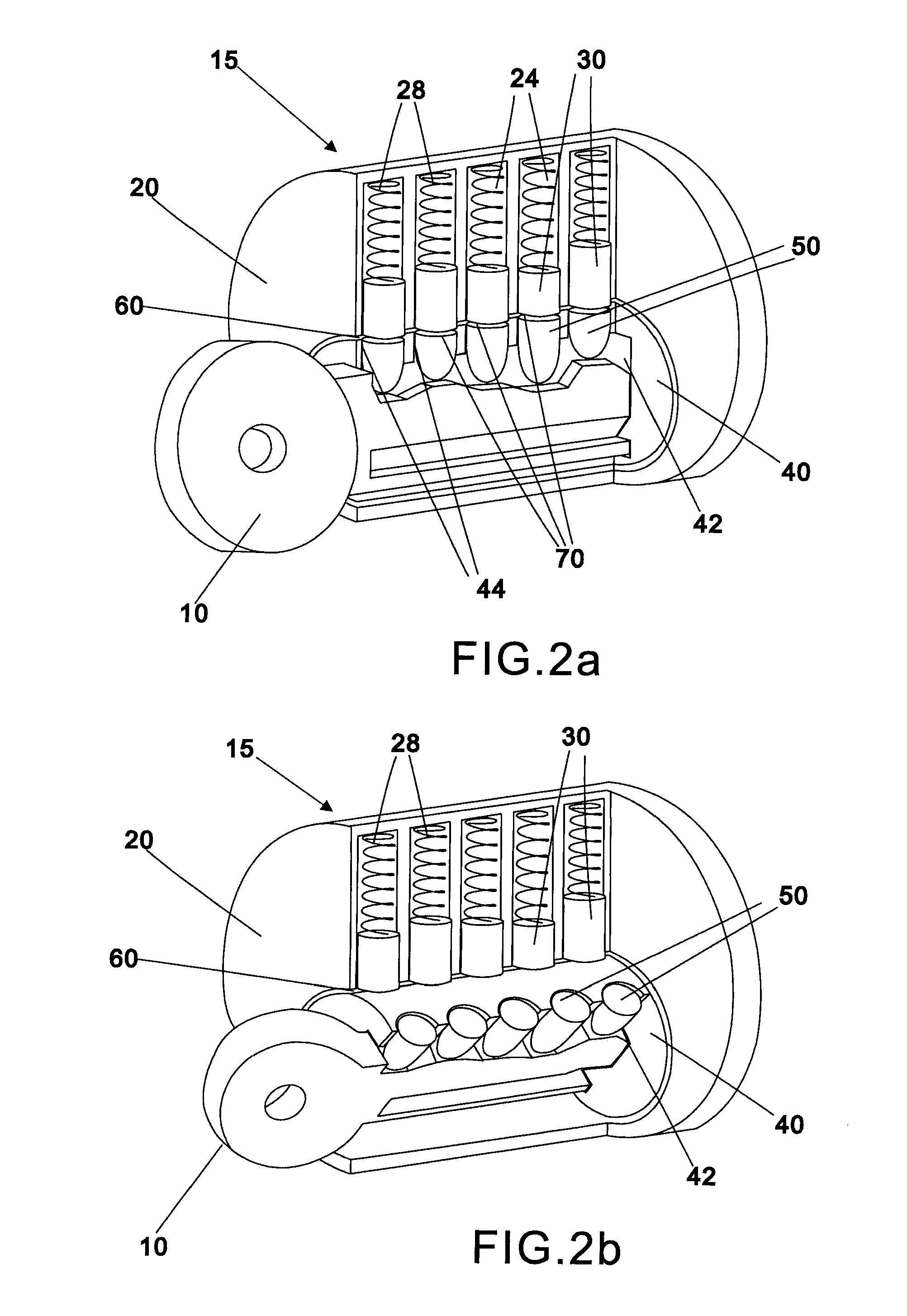
[0016]As shown in FIG. 1, a pin tumbler lock 15 includes a first lock member and a second lock member. The first lock member may be an annular shell 20. The shell 20 has at least one radial first bore 24. Each of the first bores 24 contains a first pin 30 of different sizes. A biasing device 28, for example, an ordinary spring, is disposed at the end 24a of the first bore 24 distal from the axis of the shell 20. The other end 24b of the bore 24 is an opening 26.

[0017]The second lock member may be a plug 40. In this embodiment, the plug 40 is cylindrical and is surrounded by shell 20. An interface surface 60 is formed between the shell 20 and the plug 40. There is a keyhole 42 on the plug 40 for the insertion of a key 10. The keyhole 42 is connected with at least one radial second bore 44 on the plug 40 at one end 44a of the second bore 44. The other end 44b of the second bore 44 is an opening 46, which corresponds to the opening 26 of the first bore 24. Each of the second bores 44 c...


PUM


Abstract

A pin tumbler lock, operating between a locked position and a released position, comprising a first lock member having at least one first bore with a biasing device and a first pin deposing in the first bore, and a second lock member engaging with the first lock member, forming an interface surface with said first lock member. The second lock member has at least one second bore with a second pin disposed in the second bore, and is aligned with the first bore for receiving the first pin in the locked position. At least one pin is magnetized, and the corresponding second pin is magnetic permeable, such that, when the pins are mobilized by an external force, the magnetized pin remains attracted to the corresponding magnetic permeable pin. No open space between the pins is formed at the interface surface to release the lock members.

Description

CROSS REFERENCE TO RELATED APPLICATIONS[0001]The present patent application claims priority from and the benefit of Hong Kong Patent Application No. 06113261.9, filed Dec. 1, 2006, and entitled PIN TUMBLER LOCK, which prior application is hereby incorporated herein by reference.FIELD OF THE INVENTION[0002]The present invention relates to a pin tumbler lock.BACKGROUND OF THE INVENTION[0003]A pin tumbler lock is a type of lock commonly used, for example, in doors of houses. A pin tumbler lock includes a housing shell and a plug forming an interface surface. The shell and the plug each contain a number of radial bores corresponding with those in each other. Each bore in the shell contains a first pin and each bore in the plug contains a second pin. In the locked position, a biasing device in each of the bore pushes the first pin against the second pin, such that a pin in each bore is positioned across the interface surface between the plug and the shell to bolt the lock. When the corre...

Claims


Application Information

Patent Timeline
Patent Type & Authority Applications(United States)
IPC IPC(8): E05B27/04
CPCE05B47/0044E05B27/0057Y10T70/7605
Inventor WONG, CHEUK HANGLAU, TAK SHINGLAU, TAK KIN
Owner JANES LOCK HK
Why Eureka
Try Eureka