Light plate and backlight module based on the light plate

A technology for a backlight module and a light guide plate, applied in the field of light guide plates, can solve the problems of reducing the light utilization efficiency of the known backlight module 100, difficult to control the light exit angle, difficult to adjust the brightness and uniformity, etc.

Active Publication Date: 2011-11-09
AU OPTRONICS CORP
View PDF0 Cites 0 Cited by
  • Summary
  • Abstract
  • Description
  • Claims
  • Application Information

AI Technical Summary

Problems solved by technology

In addition, the light (such as light 114) transmitted to the sandblasting structure 125 will be diffused, but part of the diffused light (such as light 115) cannot exit from the light-emitting surface 124, so it is known that the light-emitting efficiency of the light guide plate 120 is poor, which will Reduce the light utilization efficiency of the known backlight module 100
In addition, the use of the sandblasting structure 125 will make it difficult to control the light emitting angle, resulting in difficulty in adjusting the brightness and uniformity, and the light emitting surface 124 of the light guide plate 120 is likely to produce obvious bright areas (or bright lines) and dark areas (or dark lines) )

Method used


Image

  • Light plate and backlight module based on the light plate
  • Light plate and backlight module based on the light plate
  • Light plate and backlight module based on the light plate

Examples


Embodiment Construction

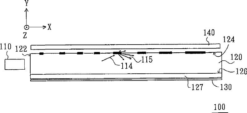
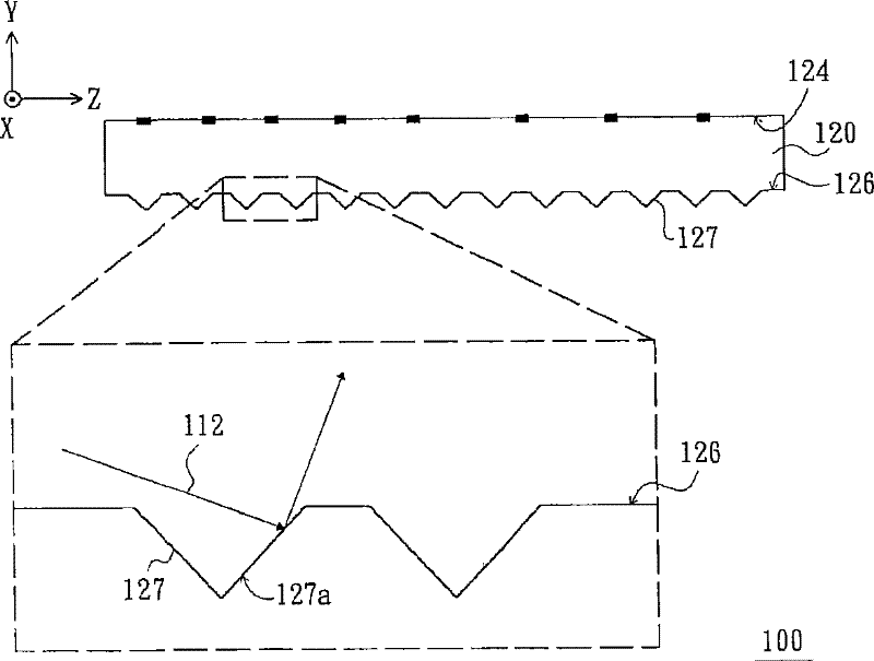
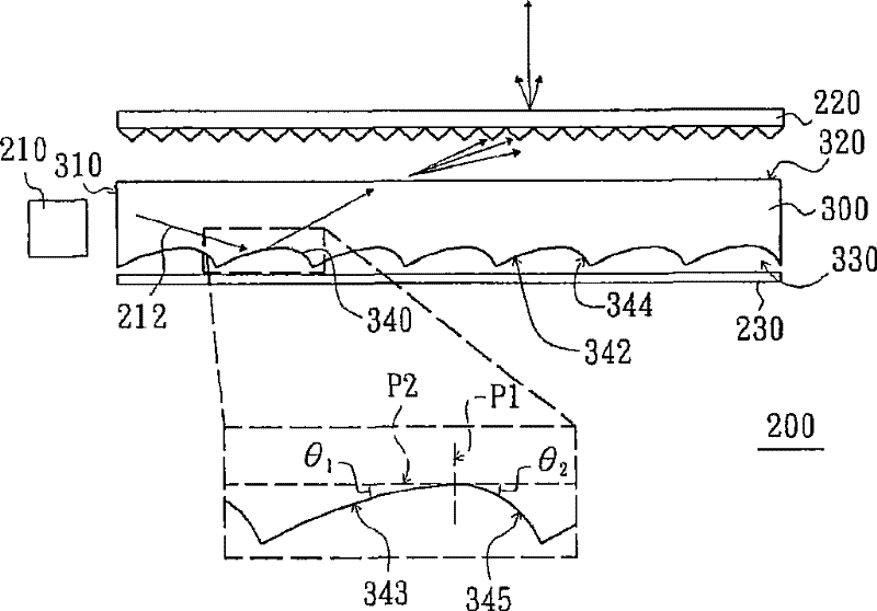
[0059] figure 2 is a schematic cross-sectional view of a backlight module according to an embodiment of the present invention, and image 3 yes figure 2 Three-dimensional schematic diagram of the light guide plate. Please refer to figure 2 and image 3 , the backlight module 200 of this embodiment includes a light source 210 , an optical sheet 220 and a light guide plate 300 . The light guide plate 300 has a light incident surface 310 , a light exit surface 320 and a bottom surface 330 , wherein the bottom surface 330 is opposite to the light exit surface 320 , and the light incident surface 310 is connected between the light exit surface 320 and the bottom surface 330 . The light source 210 is disposed beside the light incident surface 310 , and the optical sheet 220 is disposed above the light exit surface 320 . The optical sheet 220 is, for example, a prism sheet, but not limited thereto. For example, the optical sheet 220 can also be a diffusion sheet, or a combin...


PUM


Abstract

The invention provides a light guiding plate and a backlight module which is based on the light guiding plate; the light guiding plate is provided with a light inlet surface, a light outlet surface and a bottom surface, wherein, the bottom surface faces to the light outlet surface; the light inlet surface is connected between the light outlet surface and the bottom surface; the bottom surface or the light outlet surface is provided with a plurality of light guiding units; each light guiding unit is provided with a first curved surface and a second curved surface which are connected with each other; the first curved surface and the second curved surface are concave surfaces or convex surfaces; in a profile which is vertical to the light inlet surface and passes through the first curved surface and the second curved surface, the first curved surface and the profile are crossed at the first curve; the second curved surface and the profile are crossed to a second curve; the radius of curvature of the first curve is more than that of the second curve; the light guiding plate and the backlight module can adjust the light outlet direction of the light beam by controlling the radius of curvature of the first curved surface and the second curved surface of each light guiding unit, thus improving the light outlet efficiency of the light guiding plate further; therefore, the backlight module which uses the light guiding plate has good optical utilization ratio; in another words, the backlight module can provide surface light source with high brightness.

Description

technical field [0001] The invention relates to a surface light source device, and in particular to a backlight module and a light guide plate used in the backlight module. Background technique [0002] With the advancement of flat panel display technology and the advantages of light weight, small size and power saving of flat panel display devices, flat panel display devices have become more and more popular. Common flat panel display devices include liquid crystal display devices, plasma display panels (plasma display panel, PDP), organic light emitting diode display devices (organic light emitting diode display, OLED display) and electrophoretic display devices (electrophoretic display, EPD), among which The penetration rate of liquid crystal display devices is the highest. [0003] The liquid crystal display device includes a liquid crystal display panel (LCD panel) and a backlight module, wherein the backlight module is used to provide a surface light source to the liq...

Claims


Application Information

Patent Timeline
Patent Type & Authority Patents(China)
IPC IPC(8): G02F1/13357F21V8/00
Inventor 廖述珀
Owner AU OPTRONICS CORP
Why Eureka
Try Eureka