
Manganese-zinc ferrite

A manganese-zinc ferrite, weight technology, applied in the field of ferrite, can solve the problems of increased loss, low magnetic permeability, and decreased saturation magnetic flux density, and achieve low loss, high magnetic permeability, low saturation and high Effect of Magnetic Flux Density

Inactive Publication Date: 2009-03-11
KUSN NICERA ELECTRICAL APPLIANCE
View PDF0 Cites 17 Cited by
  • Summary
  • Abstract
  • Description
  • Claims
  • Application Information

AI Technical Summary

Problems solved by technology

However, the existing materials have the following disadvantages: the loss in the high frequency band is high, but if it is replaced with a low loss material in the high frequency band, the saturation magnetic flux density will become low, and the magnetic permeability will also decrease. Low (around 1500)
But in this way, it will lead to a decrease in the saturation magnetic flux density
Moreover, it is well known that in order to obtain a sufficient saturation magnetic flux density, it is necessary to increase the amount of Fe which is a basic component. 2 o 3 content, but in this case, the minimum value of power loss (Pcv min) will move to the low temperature side, which will increase the loss
Therefore, this method is not practical
The current ferrite cores cannot balance the two and are not suitable for mass production

Method used


Image

  • Manganese-zinc ferrite
  • Manganese-zinc ferrite
  • Manganese-zinc ferrite

Examples


Embodiment 1

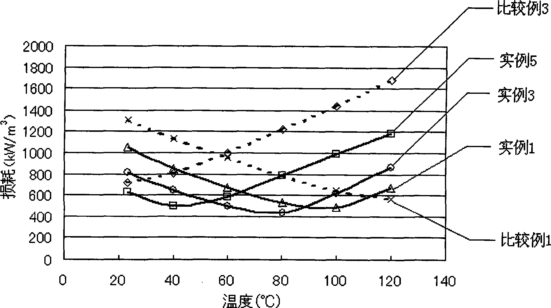
[0017] As shown in Table 1, high-purity iron oxide, manganese oxide, and zinc oxide as components were measured and mixed, and pre-fired at 950° C. for 2 hours in the air. Add 0.007% by weight of SiO to the calcined raw material 2 , 0.06% by weight of CaO, 0.04% by weight of Nb 2 o 5 , 0.7% by weight of MgO, 0.3% by weight of CoO, and pulverized with a 1.7 μm sand mill to pulverize the particle size. Thereafter, polyvinyl alcohol was added to the pulverized powder for granulation, and the obtained granulated particles were shaped into rings with an outer diameter of 24 mm, an inner diameter of 19 mm, and a height of 10 mm. Afterwards, control the peak temperature of the oxygen partial pressure in this firing, keep the temperature at 1350° C. for 4 hours and then lower the temperature. After obtaining the sample after firing, measure it with a sand mill to obtain the loss of the sample (100kHz- 200mT and 1MHz—50mT, measuring temperature 23~120℃) and the saturation magnetic f...

Embodiment 2

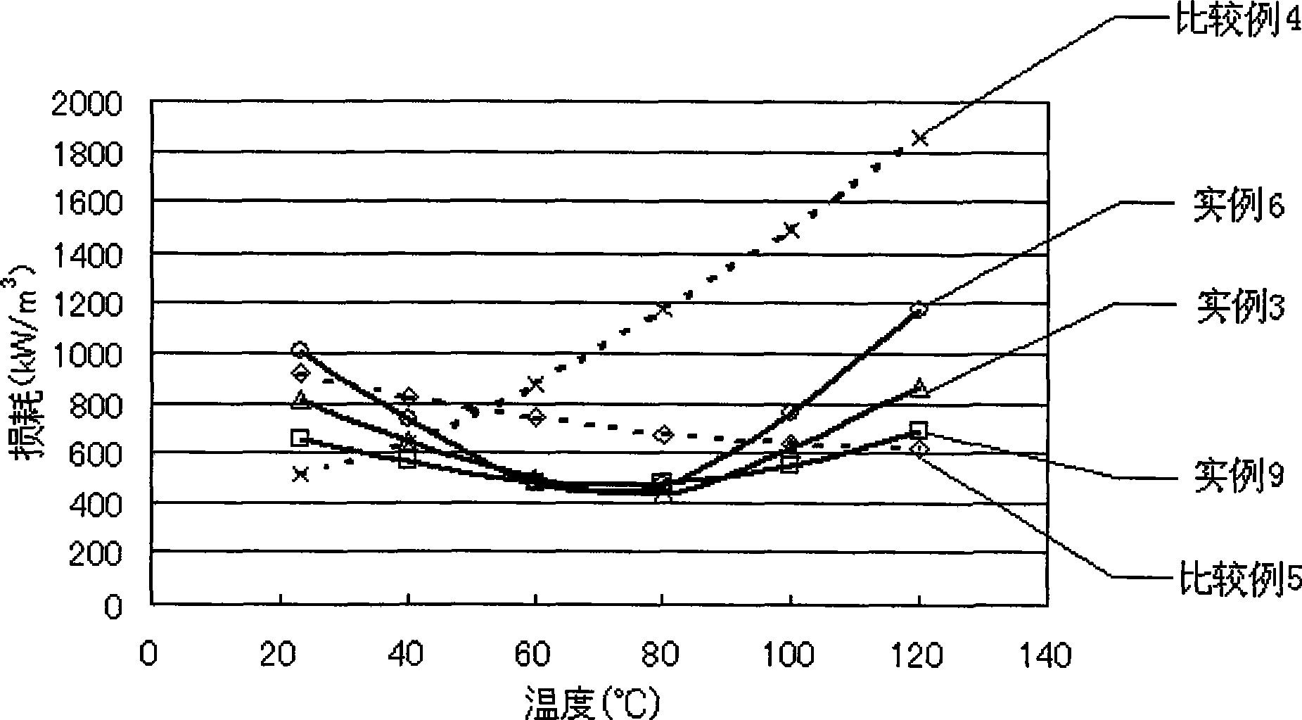
[0021] The main component of this embodiment adopts the composition combination of example 3 in embodiment 1, and SiO 2 , CaO, Nb 2 o 5 The weight ratio also adopts the ratio in embodiment 1, the ratio of MgO, CoO is adjusted, all the other are consistent with embodiment 1.

[0022] Specifically: according to Fe 2 o 3 : 55.5 mol%, ZnO: 7.0 mol%, and the balance of MnO are measured and mixed with high-purity iron oxide, zinc oxide, and manganese oxide, and pre-fired at 950°C for 2 hours in the atmosphere. And add 0.007% by weight of SiO to this calcined raw material in proportion 2 , 0.06% by weight of CaO, 0.04% by weight of Nb 2 o 5 And add MgO, CoO according to the amount shown in Table 2. Thereafter, samples similar to those in Example 1 were produced and evaluated. In Table 2, the minimum value of loss, temperature and value, saturation magnetic flux density at 23°C and 100°C, and temperature characteristics of loss at 1MHz—50mT are shown. figure 2 It is a schema...


PUM


Abstract

The invention relates to mangan-zinc ferrite, which is characterized in comprising primary components and secondary components, wherein the primary components comprise 52.0 to 59.0 mol percent of Fe2O3, 4.0 to 10 mol percent of ZnO, and the balance of MnO, the secondary components comprise 0.02 to 0.04 weight percent of SiO2, 0.01 to 0.4 weight percent of CaO, 0.01 to 0.2 weight percent of Nb2O5, 0.03 to 1.5 weight percent of MgO, and 0.1 to 0.8 weight percent of CoO. The mangan-zinc ferrite is applicable to magnetic cores of power transformers, achieves low loss and high saturation magnetic flux density and high permeability in a wide frequency range, can be widely used and can be held in other moulds for mass production.

Description

technical field [0001] The present invention relates to a ferrite, in particular to a manganese-zinc ferrite used in the magnetic core of a power transformer, which has less loss in a wide frequency band of 100 kHz to 1 MHz and has a high saturation magnetic flux density , High magnetic permeability. Background technique [0002] With the development of science and technology, electronic devices are tending to be miniaturized, light-weight and high-frequency operating frequency, which puts forward higher requirements for the performance of Mn-Zn ferrite cores. Conventional Mn-Zn ferrites contain many materials that limit the usable driving frequency, for example, materials with high magnetic permeability and low loss at frequencies around 100kHz. Corresponding to the miniaturization of the transformer, it is also important to have a high magnetic flux density. Moreover, in recent years, with the miniaturization of transformers for power supplies and the development of high...

Claims


Application Information

Patent Timeline
IPC IPC(8): C04B35/26
Inventor 西垣诚
Owner KUSN NICERA ELECTRICAL APPLIANCE
Learn More