Eureka AIR delivers breakthrough ideas for toughest innovation challenges, trusted by R&D personnel around the world.

Grain threshing separation device

A technology for threshing and separating grains, which is applied in threshing equipment, applications, agricultural machinery and implements, etc. It can solve problems such as excessive grain threshing, loss of grass discharge entrainment, poor effect of grain combing and brushing, etc., to reduce frictional resistance and increase threshing speed , The effect of small entrainment loss

Inactive Publication Date: 2009-03-11
黄宝玉
View PDF0 Cites 27 Cited by
  • Summary
  • Abstract
  • Description
  • Claims
  • Application Information

AI Technical Summary

Problems solved by technology

[0003] 1. The stirring leaves are distributed continuously from the beginning to the end on the outer surface of the drum, and the contact area with the grain is large, and the combing effect on the grain is small. Impurities, resulting in unclean threshing and grass entrainment loss
[0004] 2. The stirring blade is fixed on the drum and cannot be adjusted according to the different grains. The threshing difficulty of various grains is different, which will cause excessive threshing of some grains and insufficient threshing of other grains.
[0005] 3. The stirring blades are continuously distributed, the contact area with the grain is large, the resistance generated is also large, the power consumption is large, the combing effect on the grain is poor, and it is easy to cause grass entanglement and blockage
[0006] 4. The feeding speed is slow, and the feed port is prone to blockage when encountering lodging and nest-like grains

Method used


Image

  • Grain threshing separation device
  • Grain threshing separation device
  • Grain threshing separation device

Examples


Embodiment Construction

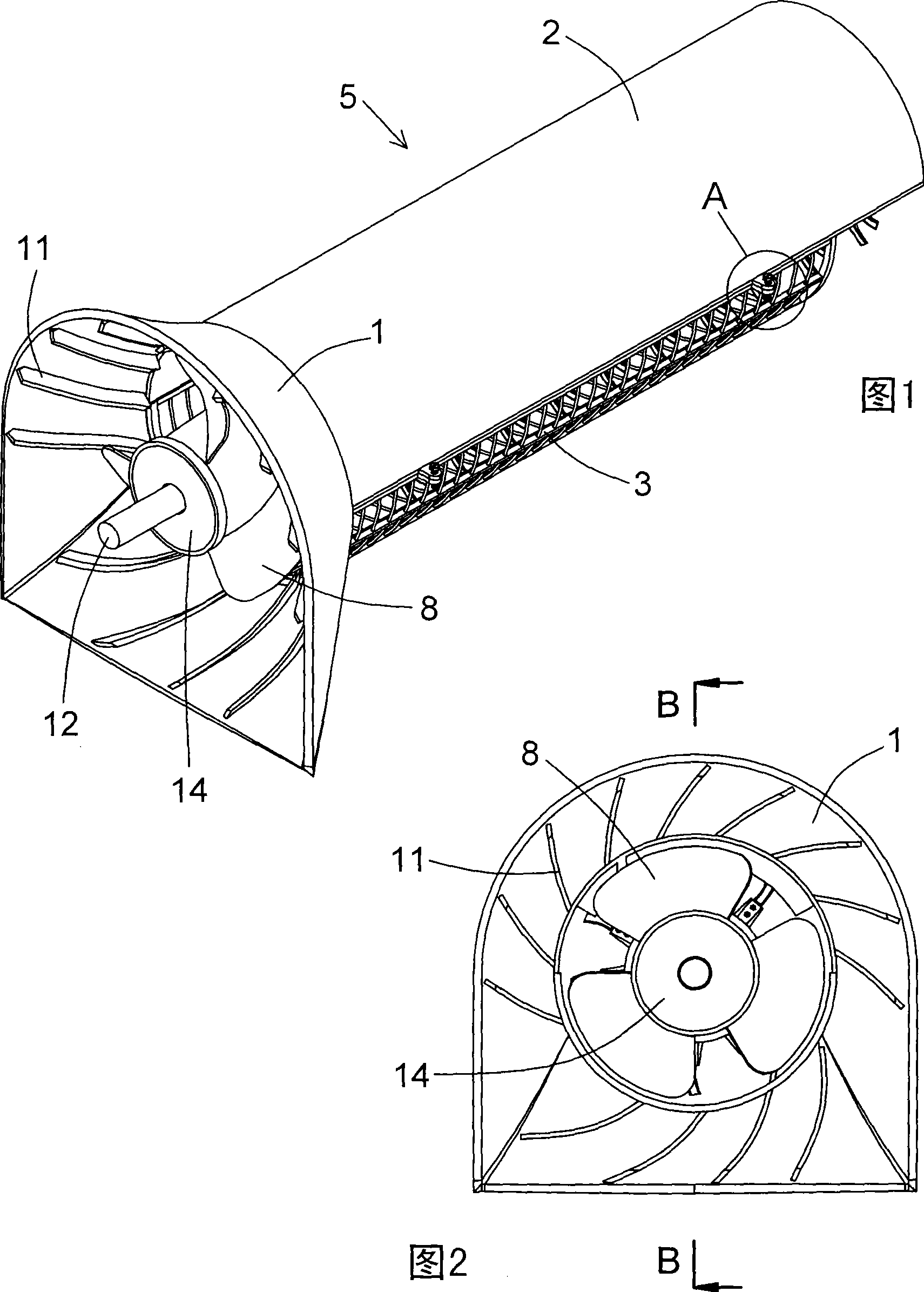
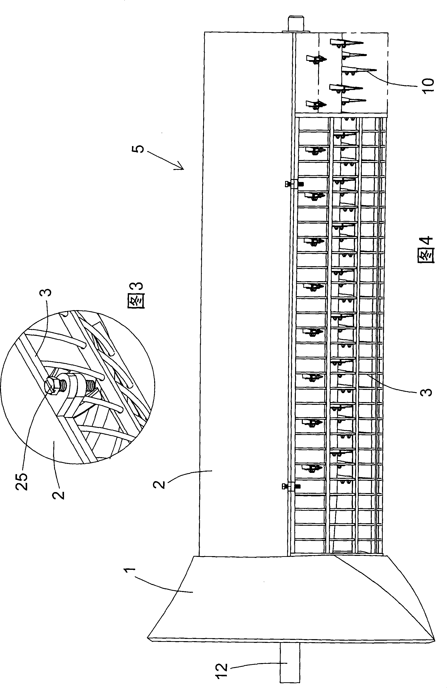
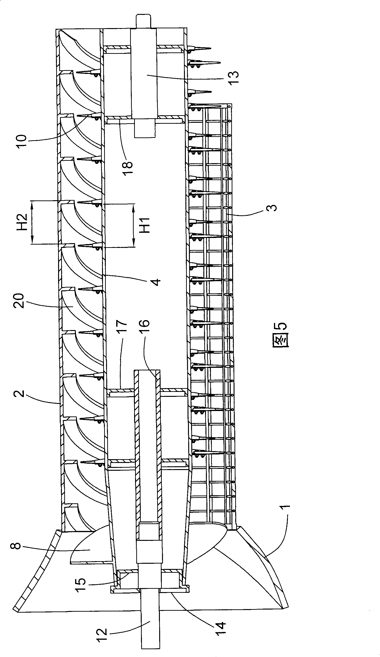
[0030] Label in the figure

[0031] 1 feed port 2 upper cover 3 concave screen 4 drum

[0032] 5 Threshing chamber 6 Front cylinder 7 Rear cylinder 8 Blades

[0033] 9 Threshing tooth seat 10 Threshing tooth 11 Curved material guide plate

[0034] 12 Front-end shaft head 13 Rear-end shaft head 14 Positioning plate 15 Coupling plate

[0035] 16 Bushing 17 Rib 18 Rib 19 Bolt

[0036] 20 Curved deflector 21 Skeleton 22 Steel wire 23 End plate

[0037] 24 Web 25 Adjusting bolt 26 Bolt 27 Nut

[0038] 28 Left half hinge seat 29 Right half hinge seat 30 Pin shaft 31 Conveying channel

[0039] Please refer to Fig. 1, Fig. 2, Fig. 3, Fig. 4, Fig. 5, Fig. 6, Fig. 7 and Fig. 8, the present invention is a kind of grain threshing and separating device, which is composed of feed port 1, upper cover 2, concave plate sieve 3 , drum 4, the upper cover 2 is semi-cylindrical, the concave screen 3 is an inverted semi-cylindrical, the upper cover 2 and the concave screen 3 are docked to for...


PUM


Abstract

A grain threshing and separating device consists of a feed inlet, an upper cover, a concave grid and a roller; a plurality of arc stock guide plates are arranged on the inner wall of the shell of the feed inlet, each arc stock guide plate is arranged at a deflection angle in relation to the radial direction of the feed inlet; the roller consists of a front section and a rear section, the front section roller takes a conical shape, the rear section roller takes a cylindrical shape, a blade for feeding is welded on the external surface of the front section roller, a plurality of groups of threshing toothholders are welded on the external surface of the rear section roller, each group of the toothholders is arranged along spiral line direction, each toothholder is fixedly connected with a threshing tooth, the toothholder is connected with the threshing tooth in a dismountable way by a bolt fastener; the two ends of the roller are respectively provided with a front spindle nose and a rear spindle nose, and a plurality of arc flow deflectors are obliquely arranged on the top of the inner wall of the upper cover. The grain threshing and separating device has the advantages of fast feeding, thorough threshing, low entrapment loss, is not likely to be blocked by twisting grass, and can thresh a plurality of grains and harvest various grains in fields.

Description

technical field [0001] The invention belongs to the field of agricultural harvesting machinery and relates to a grain threshing device matched with large, medium and small combine harvesters. Background technique [0002] The grain threshing device of the existing combine harvester is composed of a threshing chamber and an auger, the threshing chamber is composed of an upper cover and a concave plate sieve, and the auger is composed of a drum and agitating blades fixed on the outer surface of the drum and continuously distributed along the spiral direction. The auger is axially set in the center of the threshing chamber, and the grain enters along the axial direction of the auger and moves in an axial flow. Under the action of centrifugal force, the grain and straw are separated, and the grain falls through the concave plate sieve and is discharged. The threshing device of this structure has following shortcoming: [0003] 1. The stirring leaves are distributed continuously...

Claims


Application Information

Patent Timeline
Patent Type & Authority Applications(China)
IPC IPC(8): A01F7/06A01F12/18A01F12/10
CPCA01F12/22
Inventor 黄宝玉李方程涂兴刚王守境贾苹
Owner 黄宝玉
Why Eureka
Eureka Blog
Learn More