
Mount press forming mold

A stamping die and fan bone technology, applied in the field of fan bone production equipment, can solve the problems of poor processing quality, environmental pollution, low processing efficiency, etc., and achieve the effects of high production efficiency, stable forming quality, and improved safety

Inactive Publication Date: 2009-01-28
夏月明
View PDF0 Cites 2 Cited by
  • Summary
  • Abstract
  • Description
  • Claims
  • Application Information

AI Technical Summary

Problems solved by technology

[0004] The present invention aims to solve the disadvantages of low processing efficiency, poor processing quality, and environmental pollution of the existing fan frame production equipment, and provides a stamping die suitable for making fan frames by stamping

Method used


Image

  • Mount press forming mold
  • Mount press forming mold

Examples


Embodiment Construction

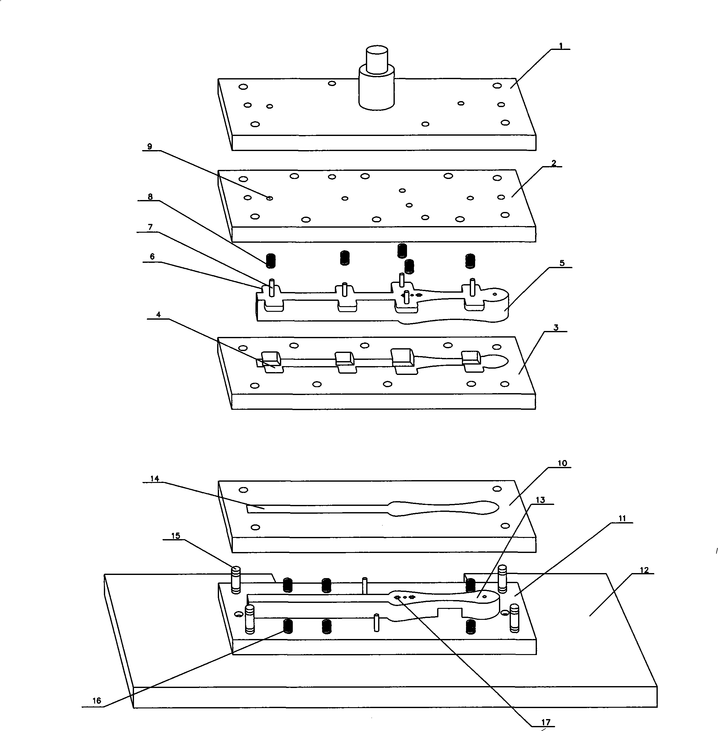
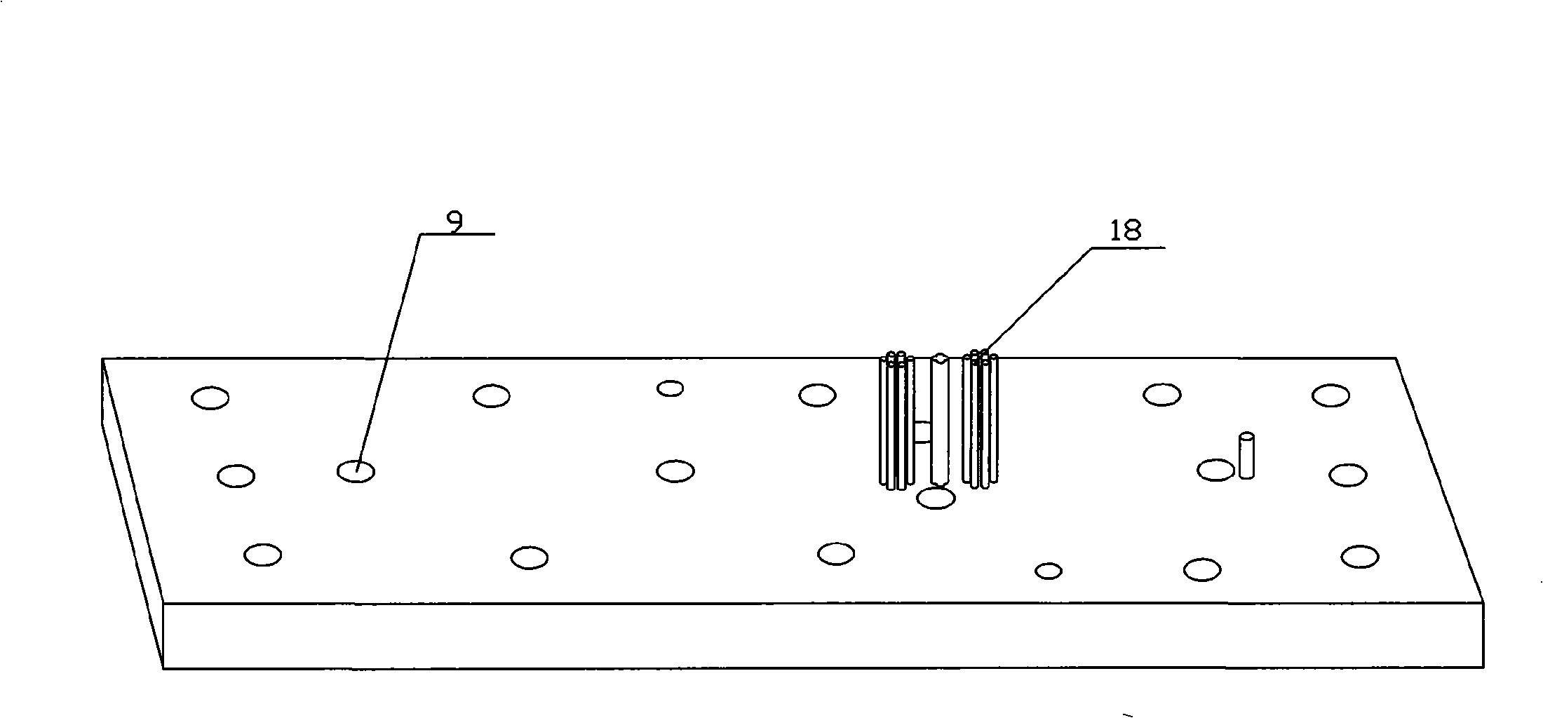
[0012] The fan rib stamping die of the present invention comprises a male mold and a female mold. The male mold is composed of an upper mold base 1, an upper middle base 2, and an upper panel 3 sequentially stacked from top to bottom. The upper mold base 1 and the upper middle base 2 are connected by pins, the upper middle seat 2 and the upper panel 3 are connected by pins, the upper panel 3 is provided with a through hole 4 adapted to the shape of the upper mold core, and the upper mold core 5 is slidably arranged in the upper panel 3, and the upper The mold core 5 is provided with a block 6 that prevents it from falling out of the upper panel 3. There is a pin 7 on the top of the upper mold core 5, and the pin 7 is passed through the guide hole 9 of the upper middle seat, and on the pin 7 The spring 8 presses the upper mold core 5 against the upper panel 3;

[0013] The female mold is composed of a lower panel 10, a lower middle seat 11, and a lower mold base 12 sequentially...


PUM


Abstract

The invention relates to a fan framework stamping mold, comprising a male mold and a female mold, the male mold consists of an upper mold seat, an upper-middle seat and an upper panel that are superposed sequentially from up to down. The upper mold seat is connected with the upper-middle seat by pins, the upper-middle seat is connected with the upper panel by pins, the upper panel is opened with a through hole, the shape of which matches with an upper mold core that is arranged in the upper panel in a sliding way, the upper mold core is provided with a stopper that prevents the upper mold core from separating from the upper panel, the top of the upper mold core is provided with a pin column that goes through the guide hole of the upper-middle seat, and a spring that is sheathed on the pin column supports the upper mold core on the upper panel closely; the female mold consists of a lower panel, a lower middle seat and a lower mold seat that are superposed sequentially from up to down, a lower mold core is fixedly connected on the lower panel, the lower middle seat is fixedly connected on the lower mold seat, the lower panel is opened with a through hole, the shape of which matches with the lower mold core that is sheathed in the through hole, the lower panel is sheathed on the pin column in the lower middle seat, and a closely supporting spring is arranged between the lower middle seat and the lower panel.

Description

(1) Technical field [0001] The invention relates to a fan frame manufacturing equipment for a folding fan. (2) Technical background [0002] The fan ribs are made of long strips of thin bamboo slices. The existing fan ribs are shaped by hand-cutting method and grinding wheel grinding method. The traditional method is not only slow in speed and difficult to stabilize the quality of the shape, but also relies heavily on the skill of the operator, making it difficult to keep the shape of the fan bone consistent; the latter first makes the grinding wheel into the shape of the side of the fan bone, and the worker grinds a stack of bamboo slices on the grinding wheel Although this method reduces the skill requirements of workers and speeds up, the grinding process of bamboo chips needs to be rinsed with water, and the rinsed water becomes sewage mixed with bamboo powder, which is very polluting to the environment and wasteful. In addition, the edge of the bamboo chip is easy to c...

Claims


Application Information

Patent Timeline
Patent Type & Authority Applications(China)
IPC IPC(8): B27M1/04B27M1/02
Inventor 程小强
Owner 夏月明
Learn More