Electrical control cable

一种控制电缆、电气控制的技术,应用在电力电缆、绝缘电缆、电气元件等方向,能够解决昂贵等问题

Inactive Publication Date: 2009-01-21
NEXANS
View PDF3 Cites 5 Cited by
  • Summary
  • Abstract
  • Description
  • Claims
  • Application Information

AI Technical Summary

Problems solved by technology

This structure is still expensive to manufacture because it employs said filler binder

Method used


Image

  • Electrical control cable
  • Electrical control cable
  • Electrical control cable

Examples


Embodiment Construction

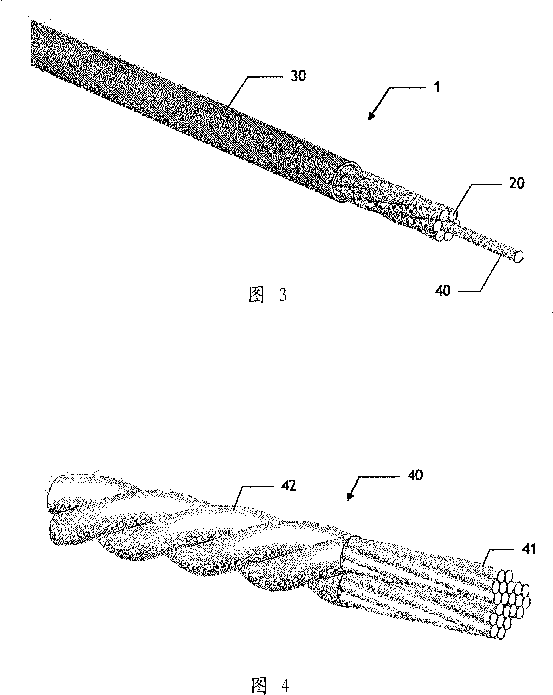
[0024] Figure 3 shows a part of a cable 1 constituting a first possible embodiment with its ends stripped to reveal the intermediate structure of said cable.

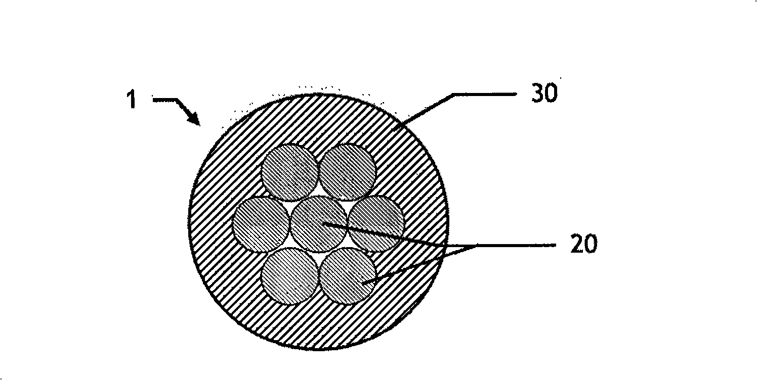
[0025] Like the prior art cables described in U.S. Patent No. 7,145,082, the cable 1 in FIG. together extend in the longitudinal direction of the central core 40 of the multi-fiber aggregate.

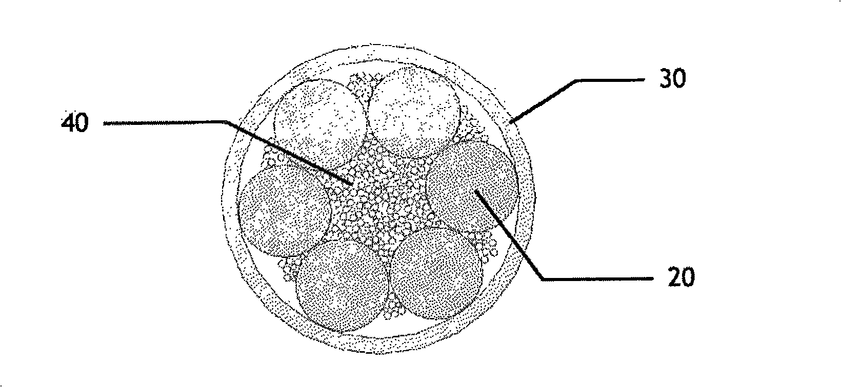
[0026] However, since these strands are evenly and concentrically distributed around the core 40 , in contact with each other and with the core in pairs, the number of strands 20 used is reduced. In the non-limiting embodiment shown, the number of these strands 20 is six. For the core and the rest of the strands, the number of whole copper strands must naturally be adapted to wrap around the core in a single layer.

[0027] The polymeric fibers of the core 40, for example composed of aramid fibers, are secured to each other only by an external adhesive coating to form a non-metallic monolithic structure. This step in the manuf...


PUM

PropertyMeasurementUnit
diameteraaaaaaaaaa

Abstract

The application relates to an electric control cable (1), which comprises multiple polymer fiber cores (40), multiple cable strands (20) made of conducting material extended along the longitudinal direction of the cores and an exterior insulating sheath. According to the invention, the cable strands (20) are arranged around the cores uniformly and concentrically connecting to each other in pair while connecting to the cores; the fibers of the cores are fixed together to form a nonmetallic integral structure in the steps of arranging the fibers into multiple components, twisting the fibers in each component, and twisting the all the components one by one into a whole helical structure. The invention can keep the used copper cable strands in limited quantity, while ensure the pressure operation is reliable.

Description

technical field [0001] This invention relates to electrical control cables, or power cables, for the transmission of electricity. [0002] Such cables are used in various industrial fields, such as the automotive industry, where they are assembled in bundles to supply power to different parts of equipment. Therefore, these cables need to have the lightest possible weight and be compact while maintaining good mechanical strength. Background technique [0003] Traditionally, these cables consist of a plurality of copper strands, generally twisted together to form twisted strands to increase the flexibility of said cable, and surrounded by an insulating sheath, obtained for example by extrusion. figure 1 An example of a cable 1 made of seven identical copper strands 20 surrounded by an insulating sheath 30 of a circular portion is shown, seen in cross section. To give a concrete idea, the cable is typically about 1.6mm in diameter and each copper strand 20 is about 0.3mm in d...

Claims


Application Information

Patent Timeline
Patent Type & Authority Applications(China)
IPC IPC(8): H01B7/00H01B7/17H01B9/00
CPCH01B7/0009H01B7/1825H01B9/00
Inventor 弗朗西斯·德布拉迪斯劳伦特·特里布特斯蒂芬妮·莫里斯
Owner NEXANS
Why Eureka
Try Eureka