Method for verifying whether detection result of detection device is correct or not
A technology for detecting equipment and detection results, applied in static memory, instruments, etc., can solve the problems of low chip power supply voltage, large influence range, and inability to see the underlying structure, etc., and achieve the effect of precise positioning
- Summary
- Abstract
- Description
- Claims
- Application Information
AI Technical Summary
Problems solved by technology
Method used
Image
Examples
Embodiment Construction
[0011] A preferred embodiment of the method for verifying whether the detection result of the detection device of the present invention is correct will be described in further detail below in conjunction with the accompanying drawings.
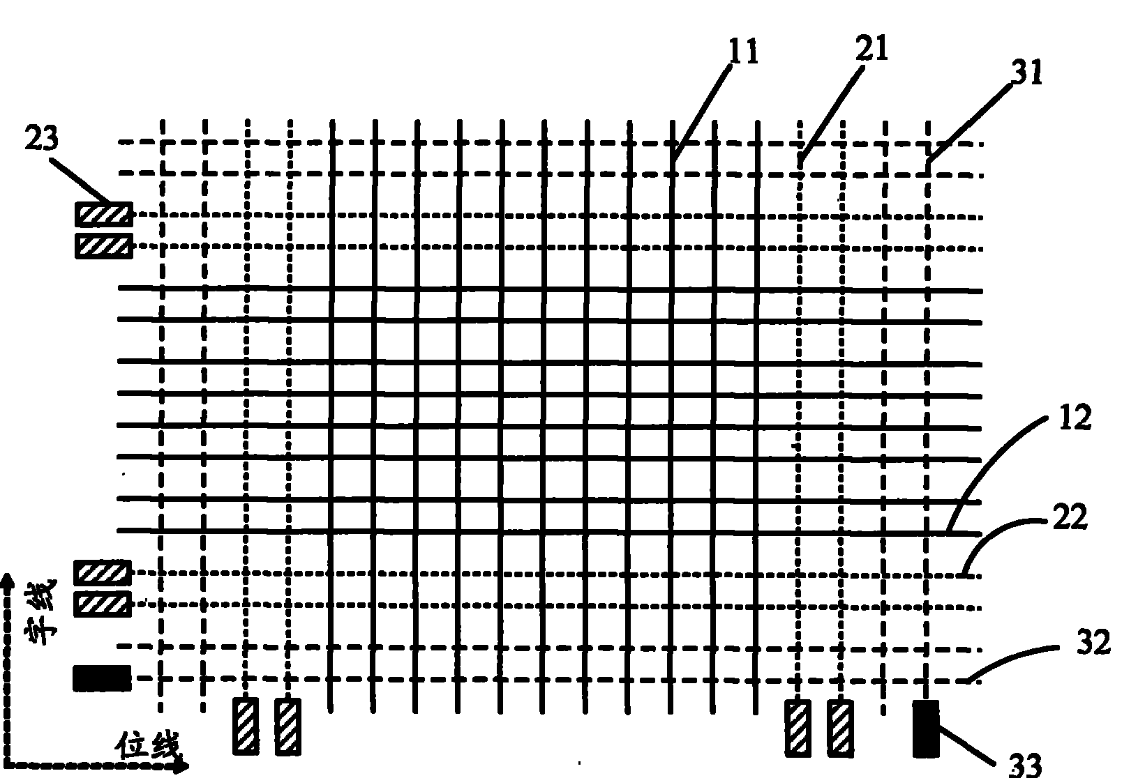
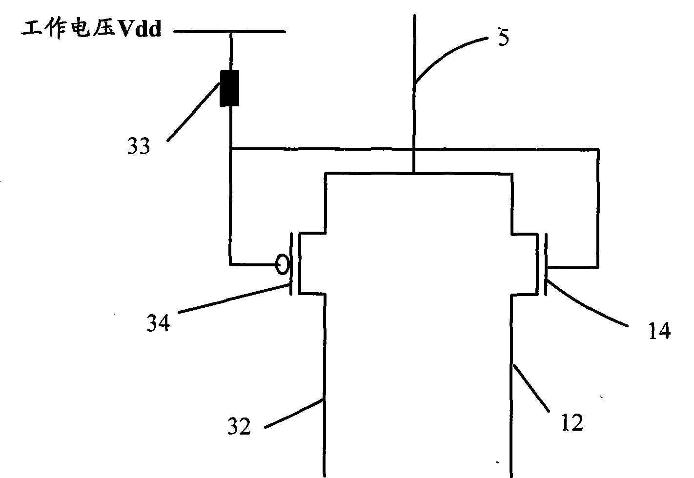
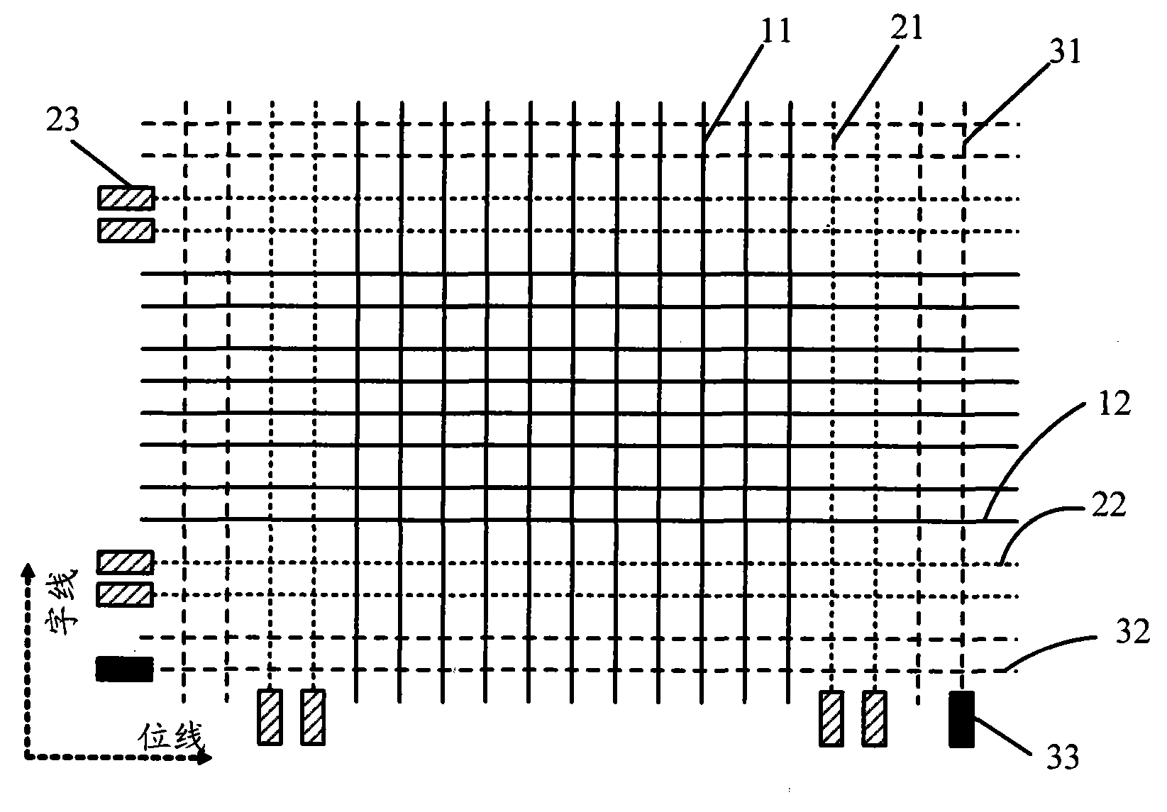
[0012] figure 1 It is a simplified schematic diagram in the form of a chip matrix, where the horizontal bit line is the bit line, the vertical word line is the word line, and the intersection of each bit line and each word line is a memory cell. A chip usually includes a working area and a dummy area (dummy) and a spare area (redundancy) located on the periphery of the working area. The active area includes bit lines 12 and word lines 11 . The dummy area includes the bit line 32 and the word line 31, both of which are located in the outermost layer of the working area of the chip, which protect the working area and do not participate in the actual circuit work. The spare area includes bit lines 22 and word lines 21. The spare area is opera...
PUM
 Abstract
Description
Claims
Application Information
 - R&D
- Intellectual Property
- Life Sciences
- Materials
- Tech Scout
- Unparalleled Data Quality
- Higher Quality Content
- 60% Fewer Hallucinations
Browse by: Latest US Patents, China's latest patents, Technical Efficacy Thesaurus, Application Domain, Technology Topic, Popular Technical Reports.
© 2025 PatSnap. All rights reserved.Legal|Privacy policy|Modern Slavery Act Transparency Statement|Sitemap|About US| Contact US: help@patsnap.com


