
Optical measurement device

A technology for optical measurement equipment and detection equipment, which is applied to measurement devices, optical devices, scattering characteristics measurement, etc.

Inactive Publication Date: 2009-01-14
KONINKLIJKE PHILIPS ELECTRONICS NV
View PDF2 Cites 3 Cited by
  • Summary
  • Abstract
  • Description
  • Claims
  • Application Information

AI Technical Summary

Problems solved by technology

[0014] Therefore, the Parousiameter discussed above is not suitable for inspection of small surface areas of larger objects and samples, and is not suitable for inspection of non-flat surfaces

Method used


Image

  • Optical measurement device
  • Optical measurement device
  • Optical measurement device

Examples


Embodiment Construction

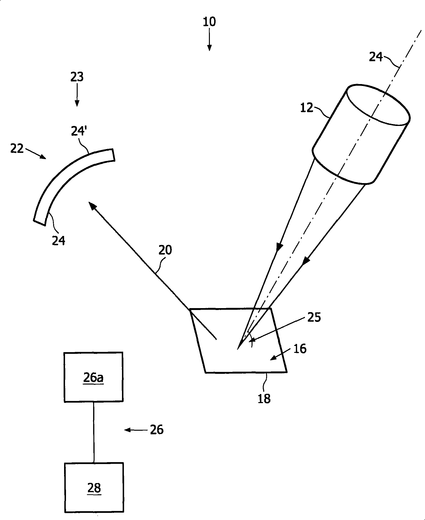
[0079] exist figure 1 In , a schematic diagram of the measuring principle of an optical measuring device 10 (called Parousiameter) is shown. The optical measuring device 10 is suitable for examining the surface of a sample, wherein as a result of the measurement the optical appearance of the surface is obtained.

[0080] Optical measuring devices using the measuring principle are known as Parousiameters. Two-dimensional images are known as Parousiagrams. The word "Parousiameter" is derived from the Greek word "parousia" for optical appearance.

[0081] Hereinafter, the measurement principle of this optical measurement device 10 will be explained.

[0082] The optical measurement device 10 includes an illumination device 12 for directing an illumination beam 14 onto a surface 16 of a sample 18 . Illumination beam 14 is scattered and / or reflected at the sample, resulting in response beam 20 , wherein the scattered and / or reflected response beam 20 is intercepted by screen 22...


PUM

PropertyMeasurementUnit
angle of incidenceaaaaaaaaaa

Abstract

The invention relates to an optical measurement device (10) for measuring an optical appearance of a surface (16) of a sample (18), in particular the surface (16) of a human skin, comprising a measuring head (30) which can be brought into contact with the surface (16) of the sample (18), the measuring head (30) comprising: an illumination device (12, 46) for illuminating the surface (16) with an illumination beam (14); a detection device (23) for detecting a response beam (20), wherein the response beam (20) is the response of the sample (18) to the illumination beam (14). The detection device (23) comprises a screen (22, 52) for intercepting the response beam (20), wherein the screen (22, 52) extends approximately a quarter hemisphere in order to realize measuring head (30) with a small contact area with the surface.

Description

technical field [0001] The present invention relates to an optical measuring device for measuring the optical appearance of a surface of a sample, especially the surface of human skin, the optical measuring device comprising a measuring head which can be brought into contact with the surface of the sample, wherein the measuring head comprises: an illumination device for for illuminating the surface with an illumination beam; and a detection device for detecting a response beam, wherein the response beam is an illumination response of the sample to the illumination beam. Background technique [0002] In the following, an object called "sample" exhibits an optical appearance, especially the surface of the object. The optical appearance of the surface of the sample is a result of how the surface responds to light from the environment, in particular the optical appearance is determined by the sum of the total response of the surface to light incident on the surface, hereinafter ...

Claims


Application Information

Patent Timeline
Patent Type & Authority Applications(China)
IPC IPC(8): G01N21/47G01B11/30A61B5/103G01N21/57
CPCG01B11/303G01N21/57A61B5/0059G01N21/474A61B5/441A61B5/0064
Inventor S·瓦德曼
Owner KONINKLIJKE PHILIPS ELECTRONICS NV
Learn More