
Multi-layer anchoring process for cable stayed bridge

An anchoring method and multi-layer technology, applied in the direction of bridges, bridge parts, bridge construction, etc., can solve the problems of large amount of materials, large volume of anchors, large weight, etc. The effect of small size, weight and material usage reduction

Inactive Publication Date: 2009-01-07
SHANGHAI JIAO TONG UNIV
View PDF0 Cites 0 Cited by
  • Summary
  • Abstract
  • Description
  • Claims
  • Application Information

AI Technical Summary

Problems solved by technology

[0005] The present invention aims at the deficiencies of the existing cable-stayed bridge anchorage technology with concrete girders and tower columns, and aims to provide a multi-layered anchoring method for cable-stayed bridges, that is, multiple pressure-bearing surfaces are used to provide counterforce at the same time to balance tension. It overcomes the shortcomings of the existing cable-stayed bridge cable anchorage, such as large volume, heavy weight, and large amount of materials, and the installation is more convenient, which improves the overall economic benefits

Method used


Image

  • Multi-layer anchoring process for cable stayed bridge
  • Multi-layer anchoring process for cable stayed bridge
  • Multi-layer anchoring process for cable stayed bridge

Examples


Embodiment Construction

[0027] The embodiments of the present invention are described in detail below in conjunction with the accompanying drawings: this embodiment is implemented on the premise of the technical solution of the present invention, and detailed implementation methods and specific operating procedures are provided, but the protection scope of the present invention is not limited to the following the described embodiment.

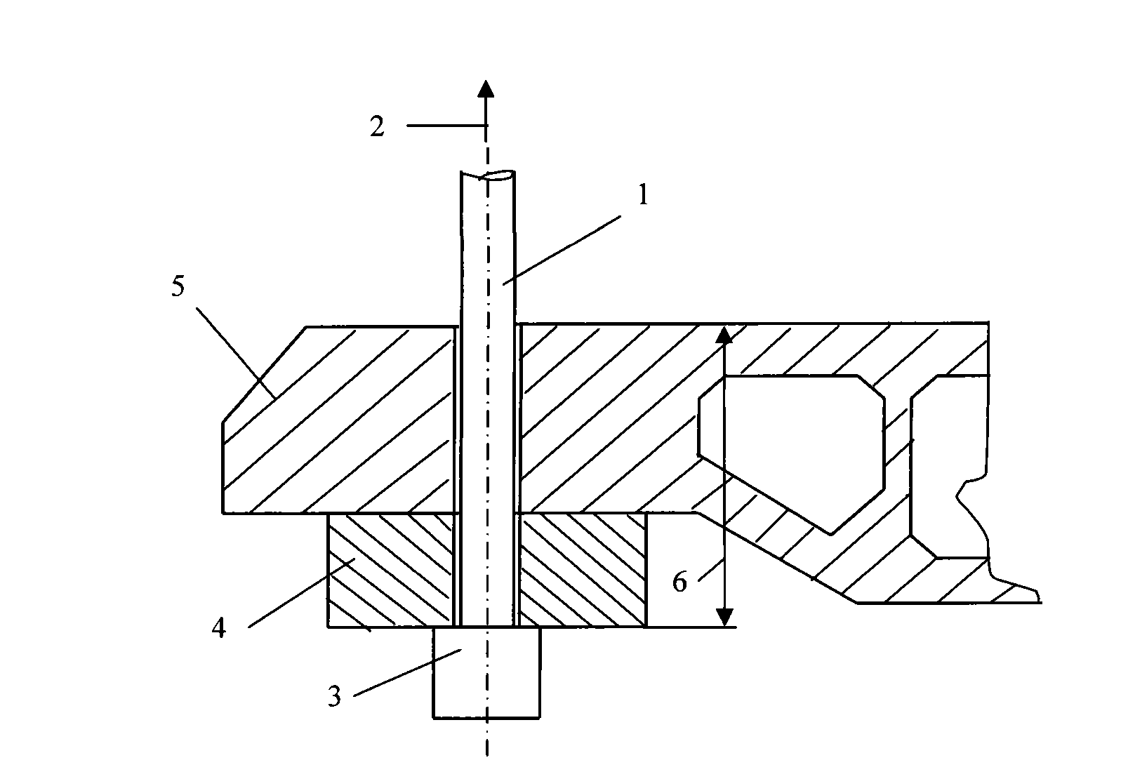
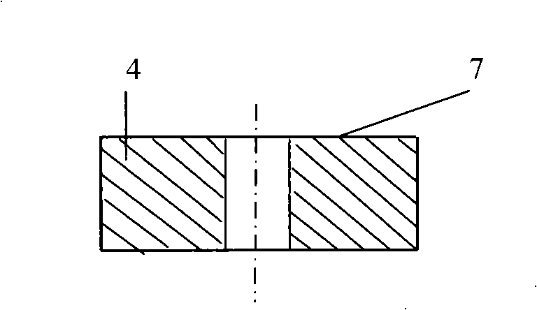
[0028] like Figure 1-2 As shown, cable 1 bears tension 2. The tension 2 is transmitted to the beam 5 through the cable anchor head 3 and the anchor structure 4, and is balanced. At this time, the total height of the anchorage between the anchor structure 4 and the beam 5 is 6. The force transmission between the anchor structure 4 and the beam 5 is through figure 2 The pressure bearing surface 7 shown is realized, and the pressure bearing surface 7 provides counterforce at this moment. If the material of the anchorage structure is steel, its compressive strength ...


PUM


Abstract

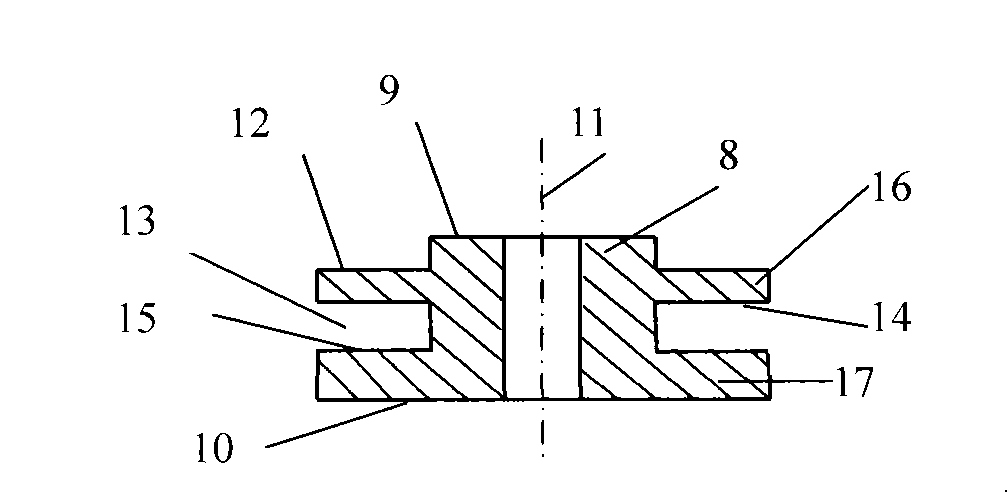
The present invention discloses a cable-stayed bridge multi-layer anchoring method in the technical field of civil engineering. Firstly, a multi-layer bearing surface anchoring object is designed, the multi-layer bearing surface anchoring object is provided with two or more than two layers of bearing surfaces, the upper surface and the lower surface parallel with each other, the center is provided with a hole penetrating the upper surface and the lower surface, an external surface groove is arranged between the upper surface and the lower surface, and the lower surface of the groove forms the bearing surface. Then the anchoring area of a main tower or a tower column is designed with the shape and the size corresponding to the multi-layer bearing surface anchoring object, the position is preserved for the installation according to the size of the multi-layer bearing surface anchoring object, and the upper part of the multi-layer bearing surface and the surrounding concrete are provided with a reinforced steel bar. Thirdly, the multi-layer bearing surface anchoring object is installed, the concrete is poured and maintained, the intensity is designed, the cable is stretched and the pulling force is adjusted, thus entering the normal working state. The present invention provides the counterforce to balance the pulling force of the cable while adopting a plurality of bearing surfaces and overcomes the defects of the large size, heavy weight and large material amount of the anchoring object of the prior cable-stayed bridge anchoring.

Description

technical field [0001] The invention relates to an anchoring method in the technical field of civil engineering, in particular to a multi-layer anchoring method for a cable-stayed bridge. Background technique [0002] A cable-stayed bridge is a cable-supported system. The stay cables need to be connected to the main girder and the bridge tower. This connection is called anchorage, and the connection area is called the anchorage area. The cable-stayed bridge transmits the force borne by the main girder from the cables to the tower columns through anchorage. On the other hand, relying on the main girder and tower column to provide the reaction force to overcome the tension of the cable. [0003] Existing cable-stayed bridge anchorage method, because anchorage structure (anchor block is its common a kind of form) all has only a single-layer bearing surface in the anchorage with girder and tower column, its shortcoming is: (1) The anchorage area is bulky, heavy, and requires ...

Claims


Application Information

Patent Timeline
Patent Type & Authority Applications(China)
IPC IPC(8): E01D19/14
Inventor 方从启
Owner SHANGHAI JIAO TONG UNIV
Learn More