Automatic manufacturing method for spiral tube

An automatic production method and technology, applied in glass production, glass molding, glass remolding, etc., can solve the problems of difficult to accurately control time, inability to guarantee product quality, and unstable lamp quality.

Inactive Publication Date: 2009-01-07
陈伯川
View PDF2 Cites 4 Cited by
  • Summary
  • Abstract
  • Description
  • Claims
  • Application Information

AI Technical Summary

Problems solved by technology

In this process, the operator is working in a heated environment, especially in summer, the working environment is harsh, which has a great impact on the health of the operator. Moreover, each process of bending the tube is completed manually, starting from the raw material of the lamp tube. In the process of bending the tube, the time is difficult to control accurately, which will cause the quality of the bent tube to be unstable
[0004] Patent No. "200710068040.X" titled "Pipe Bending Device for Energy-saving Lamp Tube Bending Machine" discloses a device that can control the two ends of the lamp tube to move toward the middle during the bending process of the lamp tube. The "200710070372.1" patent of "Light Tube Spiral Tube Bending Machine" discloses a device capable of mechanized continuous action to produce spiral lamp tubes, but the technical solution of this patent is only to realize mechanization in the process of spinning the lamp tube raw materials. In the complete production process from feeding, heating, pipe taking, shifting, spinning to removing the processed product, the work of any link depends on the time and position of the previous link. Control, if one of the links is not automated, it will inevitably become the bottleneck of the entire lamp processing. It cannot be fully automated, and it cannot really improve the efficiency of spiral lamp production, and cannot guarantee uniform and stable product quality.

Method used


Image

  • Automatic manufacturing method for spiral tube

Examples


Embodiment 1

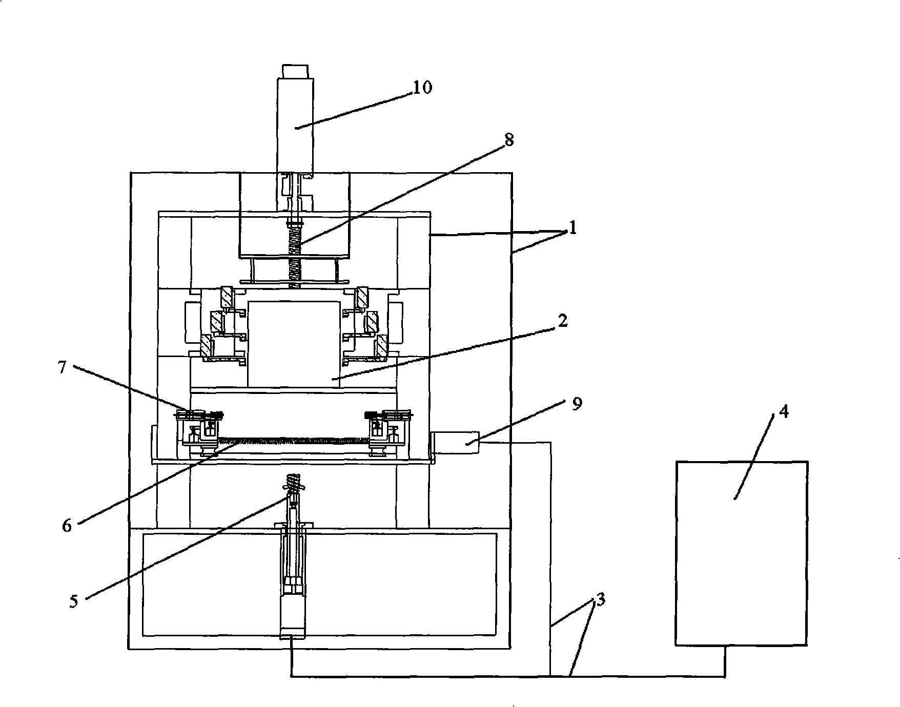
[0070] Such as figure 1 As shown, the automatic production device used in this embodiment includes a frame 1 and a heating furnace 2 installed on the frame, an inflatable claw 7, and a coil mold 5. The coil mold is provided with a spiral groove on its outer surface, which rotates Connected with the lifting device and the frame, the gas filling claw is connected with the frame 1 through the transverse screw 6 and the longitudinal screw 8, the longitudinal screw is connected with the longitudinal drive motor 10, and the transverse screw is connected with the lateral drive motor 9. The automatic production device also includes control The control device is composed of a console 4, a control circuit 3 and a driving device. The console 4 is connected to the driving device through the control circuit 3. The driving device controls the actions of the inflatable claw 7 and the coil mold 5 when processing the lamp tube Connect with each other.

[0071] The method for producing a spiral lam...


PUM


Abstract

The invention relates to an automatic production method of a spiral lamp tube. By utilizing an automatic production device of the spiral lamp tube composed of a control device, as well as a heating furnace, a coil pipe mould, and an inflated claw mounted on the machine frame, the following processing steps are accomplished by the heating furnace, the coil pipe mould, and an inflated claw controlled by the control device; the raw materials of the heating lamp tube are heated by the heating furnace; the raw materials of the lamp tube after being heated are taken out of the heating furnace by the inflated claw, and fed to the coil pipe mould; and the coiling is carried out to the lamp tube by the coil pipe mould. The control device can ensure that the numerical control automation of the production of the lamp tube is achieved, so that the temperature, the speed, the position and other parameters during the production process achieve accurate control; and an operator can be far away from the operating environment with high temperature.

Description

Technical field [0001] The invention relates to a manufacturing mechanical device and a production method of an energy-saving lamp tube, in particular to a manufacturing mechanical device and a production method of a spiral energy-saving lamp tube. Background technique [0002] In recent years, energy-saving lamps have appeared in the lighting market. Compared with the previous incandescent lamps, energy-saving lamps have many advantages: 1. High light efficiency. Luminous efficiency, or luminous efficiency, refers to the ratio of the luminous flux emitted by a light source to the electric power consumed. It can be expressed by the number of lumens per watt or LM / W (Luminous flux: refers to the amount of light emitted by the light source per unit time. It is an important indicator to measure the brightness of the lamp, expressed by LM.) Compared with ordinary light bulbs, energy-saving lamps emit light. The efficiency is increased by 5-6 times, for example, the luminous flux of a...

Claims


Application Information

Patent Timeline
IPC IPC(8): C03B23/06C03B23/045H01J9/24
CPCY02P40/57
Inventor 陈伯川
Owner 陈伯川
Why Eureka
Try Eureka