
Dynamic/static pressure electrical main shaft with automatically-rotating grinding wheel cover

A dynamic and static piezoelectric and grinding wheel technology, which is applied in the field of machine tools, can solve the problems of inconvenient operation of the grinding wheel cover and the inability to truly achieve numerical control, so as to achieve the effect of realizing numerical control automation and improving work efficiency

Inactive Publication Date: 2014-11-05
WEIHAI HUADONG AUTOMATION
View PDF6 Cites 0 Cited by
  • Summary
  • Abstract
  • Description
  • Claims
  • Application Information

AI Technical Summary

Problems solved by technology

[0002] As we all know, the grinding wheel cover installed on the front end of the electric spindle of the existing large-scale vertical grinding machine is fixed by manual rotation, and then locked and fixed by removing the screw to rotate the grinding wheel cover, which is inconvenient to operate and cannot really achieve numerical control change

Method used


Image

  • Dynamic/static pressure electrical main shaft with automatically-rotating grinding wheel cover

Examples


Embodiment Construction

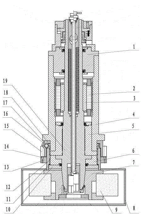
[0009] figure 1 As shown, the main shaft 19 of the present invention is installed in the sleeve 4 through the rear bearing 1 and the front bearing 5, the rotor 3 and the stator 2 are also installed between the main shaft 19 and the sleeve 4, and the grinding wheel chuck 7 is fixed on one end of the main shaft 19, and the grinding wheel A grinding wheel 9 is fixed on the chuck 7, a grinding wheel cover 8 is installed outside the grinding wheel 9, a fixed sleeve 18 and a rotating sleeve 11 are installed on the sleeve 4, a locking disc 13 is installed in the middle of the rotating sleeve 11, and a worm wheel is fixed on the upper part of the rotating sleeve 11 Mechanism, the lower part of the rotating sleeve 11 is fixed with the grinding wheel cover 8, the worm 16 and two locking cylinders 15 are installed on the fixed sleeve 18, the end of the worm 16 is driven by a servo motor 17, and the worm 16 meshes with the worm gear mechanism to lock The end face of the disc 13 is evenly ...


PUM


Abstract

The invention relates to a dynamic / static pressure electrical main shaft with an automatically-rotating grinding wheel cover and belongs to the field of machine tool fittings. The dynamic / static pressure electrical main shaft comprises a stator, a rotor, a rear bearing, a front bearing, a thrust bearing, a bushing and a main shaft, wherein a grinding wheel chuck is fixed at one end of the main shaft, a grinding wheel is fixed on the grinding wheel chuck, and a grinding wheel cover is mounted outside the grinding wheel. The invention is characterized in that a fixed sleeve and a rotating sleeve are arranged on the bushing, a locking tray is arranged in the middle of the rotating sleeve, a worm gear mechanism is fixed at the upper part of the rotating sleeve, the lower part of the rotating sleeve is fixed with the grinding wheel cover, a worm and a locking cylinder are arranged on the fixed sleeve, a servomotor driver is arranged at the end part of the worm, the worm is engaged with the worm gear mechanism, and locking holes are uniformly distributed on the end face of the locking tray; and the positions of the locking holes are corresponding to the telescopic rod of the locking cylinder. The grinding wheel cover can rotate automatically. When the grinding wheel cover rotates at a desired angle, the grinding wheel is fixed by the locking tray under the action of the locking cylinder. The invention can achieve the effect of automatic numerical control of the grinder main shaft and increase the work efficiency.

Description

technical field [0001] The invention relates to the field of machine tools, in particular to an automatic rotating grinding wheel cover type dynamic and static piezoelectric spindle. Background technique [0002] As we all know, the grinding wheel cover installed on the front end of the electric spindle of the existing large-scale vertical grinding machine is fixed by manual rotation, and then locked and fixed by removing the screw to rotate the grinding wheel cover, which is inconvenient to operate and cannot really achieve numerical control change. Contents of the invention [0003] In order to overcome the deficiencies of the prior art, the present invention provides an automatic rotating grinding wheel cover type dynamic and static piezoelectric spindle. The grinding wheel cover can automatically rotate, thereby realizing the numerical control of the grinding machine. [0004] The technical solution adopted by the present invention to solve the technical problem is: ...

Claims


Application Information

Patent Timeline
Patent Type & Authority Patents(China)
IPC IPC(8): B24B41/04
Inventor 邱玉良谭景瑞曹召东邹雪巍
Owner WEIHAI HUADONG AUTOMATION
Learn More