
Biodegradation process for ultra-thick oil waste water in oilfield

A technology for biodegradation and ultra-heavy oil, applied in the direction of separation methods, grease/oily substances/suspton removal devices, chemical instruments and methods, etc. Conditions are difficult to control and other problems, to achieve the effect of reducing the generation of oily sludge, ideal treatment effect, and efficient degradation of wastewater

Inactive Publication Date: 2010-06-02
HARBIN INST OF TECH
View PDF3 Cites 0 Cited by
  • Summary
  • Abstract
  • Description
  • Claims
  • Application Information

AI Technical Summary

Problems solved by technology

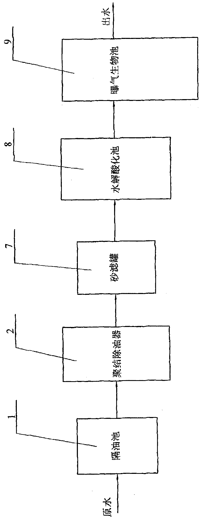
[0005] The purpose of the present invention is to solve the problem that the existing heavy oil wastewater treatment process relies too much on flocculants, which produces a large amount of oily sludge, which brings a large burden and impact on subsequent treatment, and a certain flocculant is mostly aimed at a specific wastewater , lack of wide-ranging applicability; at the same time, in view of the problems that the anaerobic-aerobic biological method that is currently researched more to treat heavy oil wastewater occupies a large area, the process is more complicated, the working conditions are difficult to control, and the treatment effect is not ideal, and then provide A biodegradation method for oil field super heavy oil wastewater

Method used


Image

  • Biodegradation process for ultra-thick oil waste water in oilfield
  • Biodegradation process for ultra-thick oil waste water in oilfield
  • Biodegradation process for ultra-thick oil waste water in oilfield

Examples


specific Embodiment approach 1

[0009] Specific implementation mode one: combine Figure 1 ~ Figure 4 with Figure 7 The biodegradation method of oilfield super-heavy oil wastewater of the present invention is completed by the following steps: A, oil separation treatment: raw water flows into the pond from one end of the oil separation pond 1, flows out from the other end, and the oil droplets with a specific gravity less than 1.0 float on the water surface, and the specific gravity The impurities greater than 1.0 sink to the bottom of the pool, and the oil droplets floating on the water surface are collected through the oil collection pipe; B. Coalescing and degreasing: the raw water after the oil separation treatment enters the mesh packing in the coalescing degreasing device 2 to gather Junction unit 3, slow flow chamber 4 and degreasing unit 5 carry out degreasing treatment, after that, raw water flows out of coalescing degreaser 2 through water outlet chamber 6 in coalescing degreasing device 2; C, sand...

specific Embodiment approach 2

[0010] Specific implementation mode two: combination Figure 7 Describe this embodiment, in step E of this embodiment: the particle size of the natural ceramsite filler 12 in the anaerobic zone 10 is 3-5mm, and the true density is 1.55g / cm 3 , the porosity is 40-45%; the particle size of the natural ceramsite filler 13 in the aerobic zone 11 is 2-4mm, and the true density is 1.58g / cm 3 , The porosity is 38-42%. The steps of other degradation methods are the same as those in Embodiment 1.

specific Embodiment approach 3

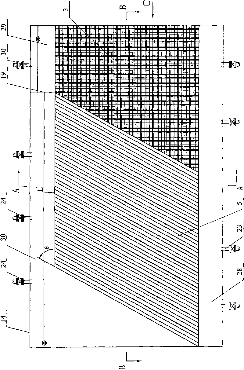
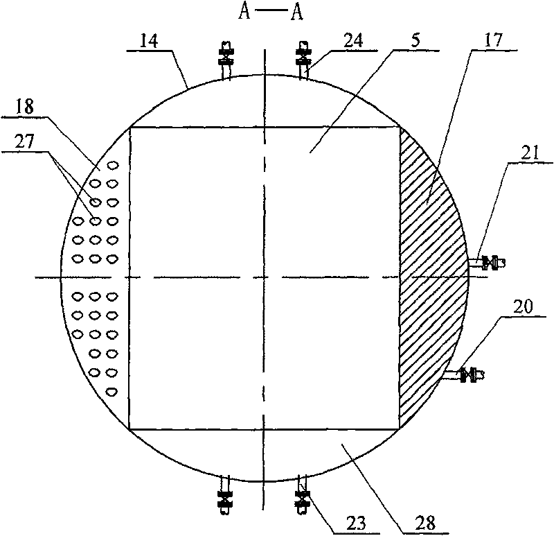
[0011] Specific implementation mode three: combination Figure 2 ~ Figure 4Describe this embodiment, in this embodiment in step B: the coalescing degreaser 2 is composed of a sealed tank body 14, a mesh filler coalescing unit 3, an oil removal unit 5, a first partition 17, a second partition 18. The third partition 19, a plurality of water inlet pipes 20, a plurality of water outlet pipes 21, a plurality of mud discharge pipes 23 and a plurality of oil discharge and exhaust pipes 24; the sealed tank body 14 is arranged horizontally, and the The mesh packing coalescing unit 3 and the degreasing unit 5 are arranged inside the sealed tank 14 along the axial direction, and the first partition plate 17 is obliquely fixed on the mesh packing coalescing unit 3 and the oil removing unit 5 Between the end faces on one side, the cavity surrounded by the mesh packing coalescence unit 3, the degreasing unit 5 and the sealed tank body 14 is divided into a water inlet chamber 25 and a water...


PUM

PropertyMeasurementUnit
particle diameteraaaaaaaaaa
densityaaaaaaaaaa
particle diameteraaaaaaaaaa

Abstract

A biological degradation method of thick oil wastewater in an oil field relates to a degradation method of thick oil wastewater in an oil field. Aiming at the problem that the prior treatment processof the thick oil wastewater excessively depends on a flocculating agent, thereby generating a large quantity of oily sludge to bring larger burden and effect on subsequent treatment; and aiming at theproblems that the floor area of the thick oil wastewater processed by adopting an anaerobic and aerobic biological method is large; the flow is complicated; the working condition is difficult to control; and the treatment effect is not ideal simultaneously, the method is realized by the following five steps: oil separation treatment, coalescent oil removal, sand filtration tank treatment, hydrolytic acidification treatment and aeration biological treatment; and raw water in a coalescent oil remover flows through a mesh-shaped filling coalescent unit, a subcritical flow chamber and an oil removal unit in sequence to be subjected to oil removal treatment; and the raw water after entering into an aeration biological tank flows through an anaerobic zone and an aerobic zone in sequence. The complete process of the method has the advantages of no secondary sedimentation tank and flocculating agent, compact structure, small floor area, simple flow, easier control of working condition, good effluent water quality and ideal processing effect, thereby realizing the standard discharge of the thick oil wastewater.

Description

technical field [0001] The invention relates to a method for degrading oil field super heavy oil wastewater. Background technique [0002] With the change of heavy oil thermal exploitation method and the increase of mining life, the amount of heavy oil sewage will increase rapidly. How to economically and rationally deal with such a large amount of heavy oil sewage has become a major problem in today's heavy oil production. Compared with thin oily sewage, refinery wastewater and other oily sewage, heavy oily sewage has the characteristics of high viscosity of water phase, poor density of oil and water, high water temperature and rich emulsion. The traditional oil extraction wastewater treatment process with oil separation-coagulation-air flotation-filtration as the main route can generally only meet the underground reinjection index, and it is difficult to meet the industrial sewage discharge standards. The coagulation effect is closely related, so the current research is ...

Claims


Application Information

Patent Timeline
Patent Type & Authority Patents(China)
IPC IPC(8): C02F9/14C02F1/40C02F3/30
Inventor 祁佩时邵志国
Owner HARBIN INST OF TECH
Learn More