
Method and device for measuring light beam orbit angular momentum spectrum

A technology for measuring beams of orbital angular momentum, which is applied in the field of measuring beam orbital angular momentum spectrum, can solve problems such as difficult adjustment, difficult adjustment, and difficult coaxial superposition of beams, so as to achieve good coaxiality and reduce the dependence on precision Effect

Inactive Publication Date: 2008-12-31
BEIJING INSTITUTE OF TECHNOLOGYGY
View PDF0 Cites 15 Cited by
  • Summary
  • Abstract
  • Description
  • Claims
  • Application Information

AI Technical Summary

Problems solved by technology

The second and third methods are extremely difficult to adjust due to the introduction of continuous rotating elements. At present, only the rotational Doppler method is used for the report of millimeter-wave orbital angular momentum, but there is no measurement report for the optical band.
Combining these three methods, it can be seen that: 1) the rotation of the beam is realized by using the Dove prism; 2) the coaxial superposition of the beam is difficult, especially when the Dove prism is rotated; 3) the rotation of the Dove prism When the optical path of the two beams is not equal, it is difficult to adjust

Method used


Image

  • Method and device for measuring light beam orbit angular momentum spectrum
  • Method and device for measuring light beam orbit angular momentum spectrum
  • Method and device for measuring light beam orbit angular momentum spectrum

Examples


Embodiment Construction

[0023] The specific embodiments of the present invention will be further described below in conjunction with the accompanying drawings.

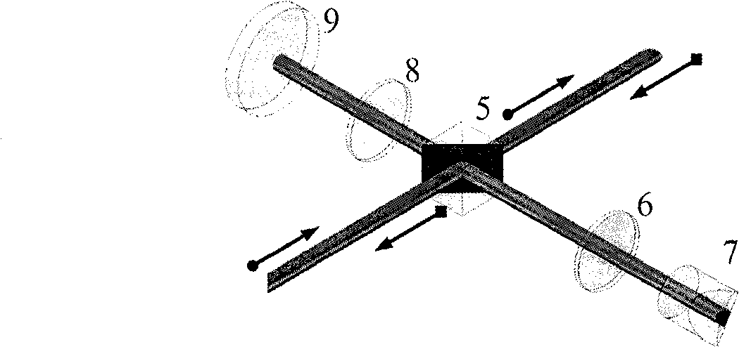
[0024] Such as figure 1 As shown, the device of the present invention consists of a device that produces two parallel light beams and realizes the coaxial superposition of these two beams of light (such as figure 2 shown) and a device that realizes coaxial rotation of two beams of light in opposite directions (such as image 3 shown) consists of two parts.

[0025] The device of the present invention comprises a light source to be measured 1, a first polarization beam splitter 2, a 1 / 2 wave plate 3, a first parallel flat crystal 4, a second polarization beam splitter 5, a first 1 / 4 wave plate 6, and a Porro prism 7 , the second 1 / 4 wave plate 8, the total reflection mirror 9, the rectangular prism 10, the phase delay film 11, the second parallel flat crystal 12 and the power detector 13. The light beam output by the light source 1 to be ...


PUM


Abstract

The invention relates to a method for realizing beam orbital angular momentum spectrometry, which belongs to the technical field of laser application. The invention consists of a light source to be tested, two polarization dispersion prisms, 1 / 2 wave plate, two parallel optical flats, two pieces of 1 / 4 wave plates, a total reflector, a rectangular prism, a Porro prism, a Pi / 2 phase delay piece and a power detector. The invention adopts the two parallel optical flats and the rectangular prism to realize the beam splitting and the beam combining of the beams, ensure the good parallelism of beam splitting light and the coaxiality of beam combining light, and realize the complete identical optical paths and attenuation of the two bunches of light. The invention adopts the polarization dispersion prism, the total reflector, the Porro prism and the two 1 / 4 wave plates to realize the beam splitting, and the two bunches of light obtained by the beam splitting rotate coaxially to further realize the coaxial superimposition of the beam and a rotating mirror image thereof. The orbital angular momentum spectrum of an incident beam can be analyzed by measuring the relation between the power of the beam combining light and the rotation of the Porro prism. The method of the invention has application value in the laser intelligence processing field.

Description

technical field [0001] The invention relates to a method and a device for measuring the orbital angular momentum spectrum of a light beam, belonging to the technical field of laser applications. Background technique [0002] There are two kinds of orbital angular momentum of a beam: angular momentum due to the polarization properties of the beam and angular momentum due to the helical phase structure of the beam. The beam angular momentum caused by the polarization properties of the beam has been known for a long time, while the orbital angular momentum of the beam has only been recognized in recent years. Studies have shown that when a beam contains an angularly-dependent phase distribution (also known as twisted phase or helical phase), such a beam has an angular momentum (called orbital angular momentum) related to the angular phase distribution. An important property of orbital angular momentum is its special quantum nature. The study shows that the orbital angular mom...

Claims


Application Information

Patent Timeline
IPC IPC(8): G01J1/00G01J9/00
Inventor 高春清刘义东高明伟齐晓庆
Owner BEIJING INSTITUTE OF TECHNOLOGYGY
Learn More