Method of lens positioning for tilt compensation, method and apparatus for reading and recording data onto an optical disc

A technology of optical disc and equipment, applied in the field of positioning of objective lens

Inactive Publication Date: 2008-12-24
KONINKLIJKE PHILIPS ELECTRONICS NV
View PDF1 Cites 0 Cited by
  • Summary
  • Abstract
  • Description
  • Claims
  • Application Information

AI Technical Summary

Problems solved by technology

This method is slow as it relies on maximizing the generated signal using a parabolic fit as a function of the tilt angle, which is varied in fixed steps

Method used


Image

  • Method of lens positioning for tilt compensation, method and apparatus for reading and recording data onto an optical disc
  • Method of lens positioning for tilt compensation, method and apparatus for reading and recording data onto an optical disc
  • Method of lens positioning for tilt compensation, method and apparatus for reading and recording data onto an optical disc

Examples


Embodiment Construction

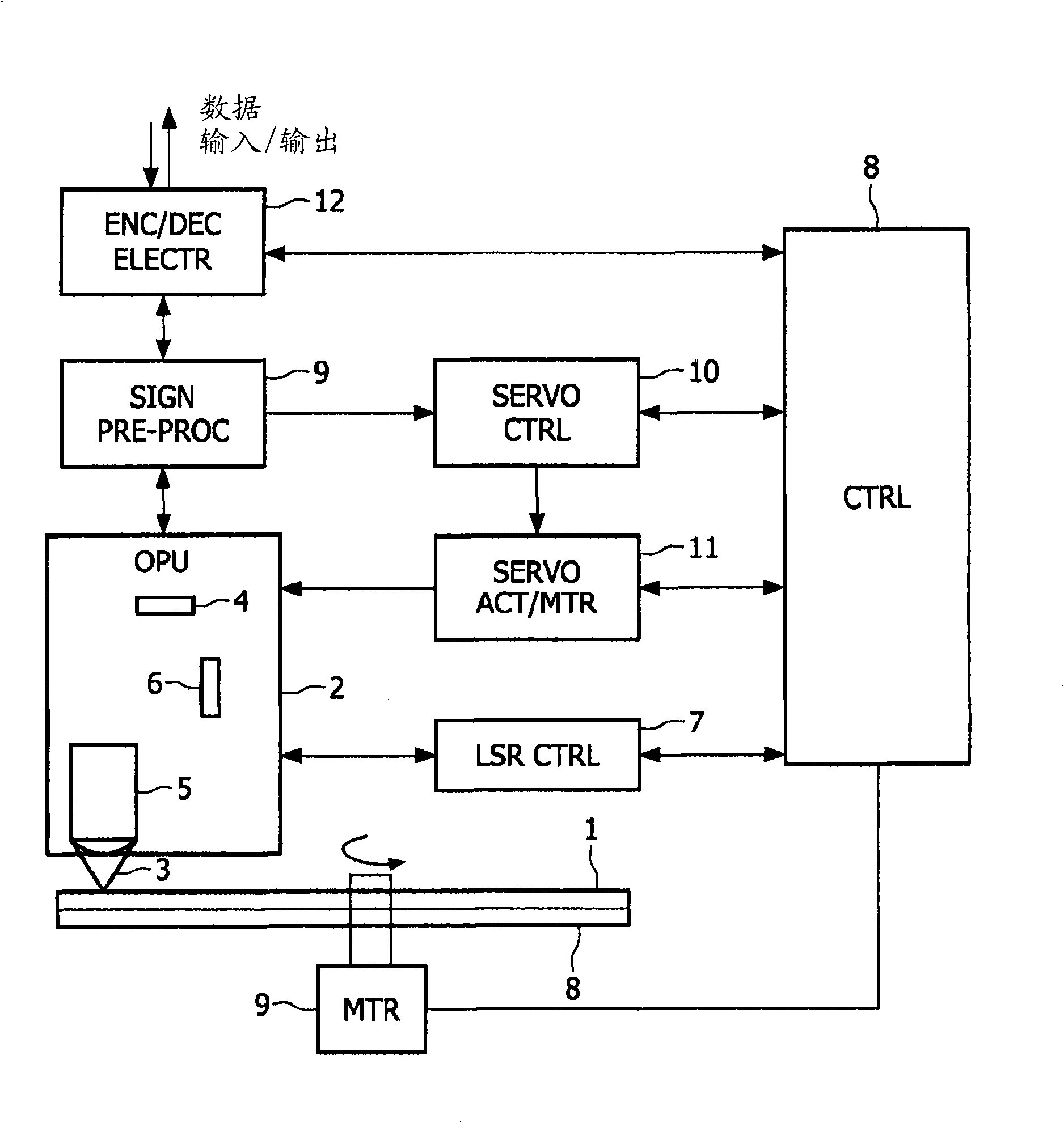
[0024] exist figure 1 A block diagram of an optical disc drive in which the invention may be practiced is shown in . A disc (1) placed on a turntable (8) is rotated by a rotatable motor (9). The rotational speed of the rotatable motor (9) is controlled by a controller (8). Encoded information is read or recorded from / to the optical disc (1) by an optical pickup unit (OPU) (2). The optical pickup unit (2) generates and focuses an electromagnetic beam (3) onto said optical disc, and the optical pickup unit receives reflected electromagnetic beams modulated by a periodic structure on the optical disc (1). Among other components, the optical pickup unit (2) includes: a laser diode (4) for generating the electromagnetic beam (3); a lens system (5) for focusing the beam onto the on the disc; and a detection system (6) comprising several photodiodes for converting the received reflected electromagnetic beam into a photocurrent. The output power of the laser is controlled by a las...


PUM


Abstract

A method of controlling the positioning of an objective lens of a lens system for controlling an optical beam used in reading and / or recording information from / onto a track of an optical disc, the method comprising steps of detecting modulated optical signals corresponding to the intensity of a reflected optical beam, the reflected optical beam being modulated by the periodic structures of the track of the optical disc, deriving a radial tilt error signal from the modulated optical signals indicative of a radial tilt, wherein the radial tilt refers to the tilt of the objective lens with respect to the optical disc in a radial direction; using the radial tilt error signal for adjusting the position of the objective lens with respect to the optical disc in a radial direction, the method characterized by using the radial tilt error signal for adjusting the position of the objective lens by means of a feedback loop. The radial tilt error signal may be proportional to a cross correlation signal between a Radial Push Pull (RPP) signal and a Central Aperture (CA) signal or a cross correlation signal between a Radial Push Pull (RPP) and a Diagonal Push Pull (DPP) signal.

Description

technical field [0001] The present invention generally relates to a method of controlling the positioning of an objective lens of a lens system in order to control a light beam for reading and / or recording information from / to a track of an optical disc. The present application also relates to a method of reading and / or recording data from / onto an optical disc and a device for reading and / or recording data from / to a track of an optical disc. Background technique [0002] Optical disc technology relies on focusing electromagnetic beams into small spots on the information layer beneath the disc's protective cover layer in order to read and / or record information. The density of information recorded in the information layer of an optical disc is continuously increasing. For example, the track pitch of a CD-type optical disk is 1.6 μm, and the track pitch of a DVD-type optical disk is only 0.74 μm but its information density is increased to 7 times. [0003] Future high-density ...

Claims


Application Information

Patent Timeline
Patent Type & Authority Applications(China)
IPC IPC(8): G11B7/095
CPCG11B7/0956G11B7/085G11B7/095
Inventor R·夫卢特斯B·殷
Owner KONINKLIJKE PHILIPS ELECTRONICS NV
Why Eureka
Try Eureka