Positioning unit

A technology of positioning unit and linear drive, which is applied to optical components, transmission devices, instruments, etc., can solve the problems of difficulty in precise positioning of components, and achieve the effect of fast and reliable positioning

Active Publication Date: 2017-05-24
安东帕有限责任公司
View PDF15 Cites 0 Cited by
  • Summary
  • Abstract
  • Description
  • Claims
  • Application Information

AI Technical Summary

Problems solved by technology

This situation leads to constant adjustment and "repositioning" of the sliding mounts of the positioning unit, whereby a particularly precise positioning of the components becomes difficult, if not even impossible.

Method used


Image

  • Positioning unit
  • Positioning unit
  • Positioning unit

Examples


Embodiment Construction

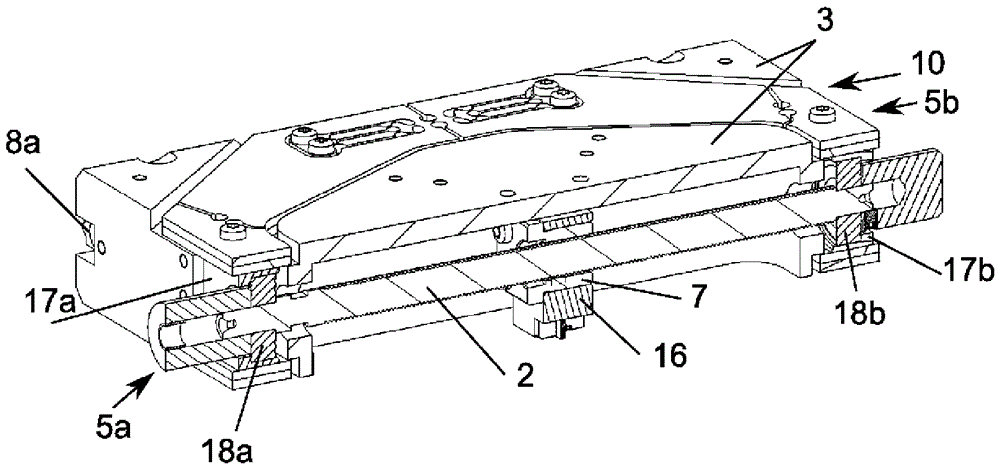
[0040] Figure 1a An embodiment of the positioning unit 10 according to the invention is shown with two compensation rods 4 a and 4 b connected via a joint 6 and arranged in an equilateral triangle with the long part of the linear drive 1 . This implementation takes the form of Figure 1b It is similarly described in the description of the drawings of the embodiment.

[0041] exist Figure 1b An embodiment of the positioning unit 10 according to the invention is shown in a schematic illustration. The positioning unit 10 has a linear drive 1 comprising a slightly longer section and a shorter section. In this embodiment, the linear drive 1 is designed as a spindle drive, the slightly longer part being the spindle 2 and the shorter part being the nut 7 . The nut 7 rests on the spindle 2 and is fixed on the slide bracket 3 . In the case of rotation of the spindle 2 , the sliding mount 3 is moved in translation along the spindle axis by means of the nut 7 . The main shaft 2 is...


PUM


Abstract

The invention relates to a positioning unit for a carriage (3) that is adjustable by way of a linear drive (1), and a base (16), wherein the linear drive (1), in particular spindle drive or linear motor, has an elongate part and a short part. According to the invention, provision is made for the positioning unit (10) to have at least two compensation rods (4a, 4b), wherein in each case two adjacent compensation rods (4a, 4b) are connected together at one end via a joint (6) and are connected at the in each case other end to the elongate part of the linear drive (1) via one of two joint arrangements (5a, 5b) that are arranged in each case at the end of the elongate part of the linear drive (1), wherein the compensation rods (4a, 4b) and the elongate part of the linear drive (1) are arranged in the form of a triangle and the angle between the compensation rods (4a, 4b) and the joint (6) is variable by a thermal change in length of the elongate part of the linear drive (1), and wherein the carriage (3) is connected to the joint (6) and the short part of the linear drive (1) is connected to the base (16), or the carriage (3) is connected to the short part of the linear drive (1) and the base (16) is connected to the joint (6).

Description

technical field [0001] The invention relates to a positioning unit for a sliding carriage adjustable with a linear drive according to the preamble of claim 1 . Background technique [0002] A linear drive usually comprises a slightly longer part and a shorter part, for example in the case of a spindle drive a spindle and a nut, which are movable with respect to each other and one of these parts is connected or connected to the carriage. Furthermore, linear drives are known from the prior art with hydraulic or pneumatic actuating devices having cylinders and pistons (with or without piston rods or linear motors). Positioning units with linear drives are used, for example, to position slide carriages on which test specimens or workpieces are mounted or fastened. In the prior art, such positioning units are also arranged and combined in two or three directions of motion orthogonal to each other, in order to enable two-dimensional or three-dimensional positioning. [0003] In ...

Claims


Application Information

Patent Timeline
IPC IPC(8): B23Q5/38B23Q5/40B23Q11/00
CPCB23Q11/0007B23Q15/18B23Q5/38B23Q5/40B23Q11/0003G02B7/008G02B21/26G02B7/005G01B5/0014F16H25/20F16H2025/204F16H2025/2075
Inventor N.拉斯
Owner 安东帕有限责任公司
Why Eureka
Try Eureka