
Yarn deflection rollers for mechanical yarn accumulators

A deflecting roller and accumulator technology, applied in the field of yarn deflecting rollers, can solve problems such as component damage

Active Publication Date: 2020-05-26
SAURER GERMANY GMBH & CO KG
View PDF16 Cites 0 Cited by
  • Summary
  • Abstract
  • Description
  • Claims
  • Application Information

AI Technical Summary

Problems solved by technology

[0019] In such a situation where the yarn to be wound can no longer be guided correctly in the yarn guide groove of the yarn deflection roller on the output side of the yarn accumulator, the yarn often abuts against the corresponding adjacent components, with the result that these components become damaged over time and need to be replaced

Method used


Image

  • Yarn deflection rollers for mechanical yarn accumulators
  • Yarn deflection rollers for mechanical yarn accumulators
  • Yarn deflection rollers for mechanical yarn accumulators

Examples


Embodiment Construction

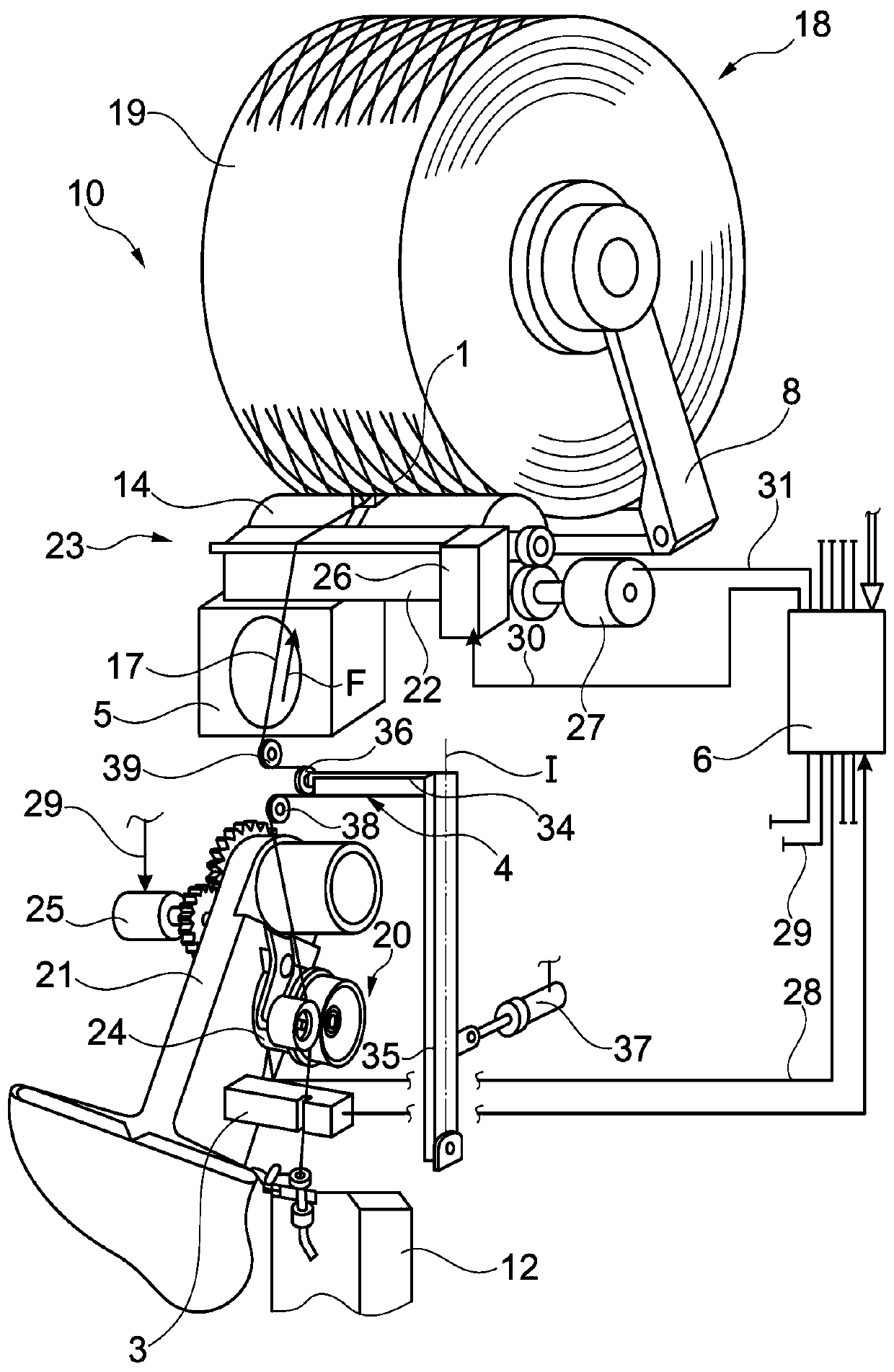
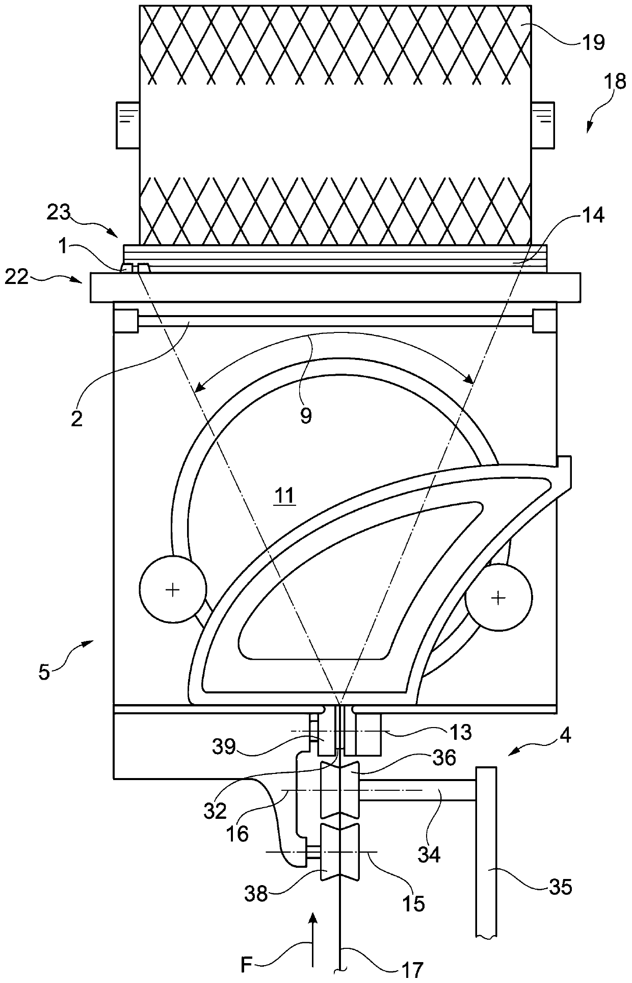
[0037] figure 1 A perspective front view of a highly schematic type is provided, showing a workstation 10 of a textile machine (in the present example an open-end rotor spinning machine) producing cross-wound bobbins. As already disclosed, such an open-end rotor spinning machine has a large number of identically configured workstations 10 of this type, which are arranged next to each other in a row. At the workstation 10, a yarn 17 is spun in each case by means of an open-end rotor spinning device 12 from a so-called sliver held in a spinning pot (not shown) and subsequently in a winding device 18. The yarn 17 is wound into a cross-wound bobbin 19.

[0038] The winding devices 18 of such workstations 10 each have: a creel 8 for holding cross-wound bobbins 19 in a rotating arrangement; a yarn traversing device 22 with a traversing yarn guide 1 which For example, it may be driven by a single motor for traversing the yarn 17 running onto the cross-wound bobbin 1; and a bobbin d...


PUM


Abstract

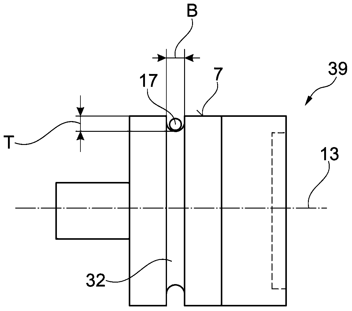
The invention relates to a yarn deflection roller (39) for a mechanical yarn energy store (4). The yarn deflection roller (39) is arranged in the area of ​​the yarn traversing triangle (9) of the workstation (10) for the production of cross-wound bobbins of the textile machine, by means of which the yarn deflection roller (39) pairs the cross-wound During the winding process of the bobbin (19), the yarn winding speed variation due to the yarn traversing occurs is compensated. According to the invention, the yarn deflecting roller (39) is arranged to have a yarn running surface (7) machined with a U-shaped yarn guiding groove (32).

Description

technical field [0001] The invention relates to a yarn deflecting roller for a mechanical yarn accumulator, which is arranged in the region of the yarn traversing triangle of a workstation for manufacturing cross-wound bobbins of a textile machine, through which the yarn The deflection rollers compensate for changes in the yarn winding speed due to yarn traversing during the winding of the cross-wound package. Background technique [0002] As already known, the workstation for producing cross-wound bobbins of a textile machine configured as an open-end rotor spinning machine has: an open-end rotor spinning device, each open-end rotor spinning device Both produce yarn at a constant delivery speed; a winding device, which ensures that: the produced yarn is wound on a winding spindle and traversed simultaneously to create a cross-wound bobbin; and a yarn accumulator, The yarn accumulator compensates for yarn winding speed and yarn tension fluctuations due to yarn traversing. ...

Claims


Application Information

Patent Timeline
Patent Type & Authority Patents(China)
IPC IPC(8): B65H59/00B65H59/34
CPCB65H59/005B65H59/34B65H2701/31B65H57/14
Inventor 伊丽莎白·克拉琴斯基
Owner SAURER GERMANY GMBH & CO KG
Learn More