Eureka AIR delivers breakthrough ideas for toughest innovation challenges, trusted by R&D personnel around the world.

Flat type evaporator radiation system

A flat plate evaporator and heat dissipation system technology, applied in indirect heat exchangers, lighting and heating equipment, cooling/ventilation/heating renovation, etc. and other problems to achieve the effect of reducing the startup temperature

Inactive Publication Date: 2008-11-26
IND TECH RES INST
View PDF0 Cites 12 Cited by
  • Summary
  • Abstract
  • Description
  • Claims
  • Application Information

AI Technical Summary

Problems solved by technology

[0007] The above-mentioned known heat pipe evaporators are all cylindrical. For planar heat sources such as electronic chips, adapter elements are still needed to convert the cylindrical surface into a plane, so as to facilitate the heat dissipation design of the planar heat source. Such a design requires more adapter elements. Uncertainty, and increasing the thermal resistance will affect the performance of heat conduction

Method used


Image

  • Flat type evaporator radiation system
  • Flat type evaporator radiation system
  • Flat type evaporator radiation system

Examples


Embodiment Construction

[0088] The present invention will be fully understood from the following examples, so that those skilled in the art can complete it, but the implementation of the present invention should not be limited by the following examples.

[0089] Please refer to FIG. 3 , which is a schematic diagram of the first embodiment of the cooling system of the present invention. In Fig. 3, a cooling system 3 includes an evaporator 31, a steam channel 33, a condensate channel 35 and a condensation area 37, wherein the evaporator 31 is a flat shell tank 310, which is composed of upper and lower covers, Usually made of a metal alloy with good thermal conductivity, it is used to be close to or in contact with an external heat source 91 to bear its thermal energy, and it includes a first capillary structure (WickStructure) 311, a steam channel 313 and a compensation chamber (Compensation Chamber) 315, and after vacuumizing, inject a liquid that is easily evaporated under a low pressure as a condens...


PUM


Abstract

The invention discloses a heat dissipation system which is used for increasing the efficiency of traditional heat conducting pipes, promoting the efficient utilization of space and reducing the temperature in starting the heat conducting pipe. The heat dissipation system comprises an evaporator, a steam channel, a condensing area and a condensate channel; wherein, one end of the steam channel is connected with the evaporator and the steam channel is used for conveying the steam from the evaporator; the other end of the condensate channel is connected with the condensing area which is used for condensing the stream into the condensate, and the condensate channel is connected with the condensing area and the evaporator and one of the condensing area and the evaporator is provided with a capillary structure; the condensate channel and the steam channel are connected with the condensing area by the evaporator; the condensate returns to the evaporator by the condensate channel and transforms into other steam by an outer heat source in the evaporator.

Description

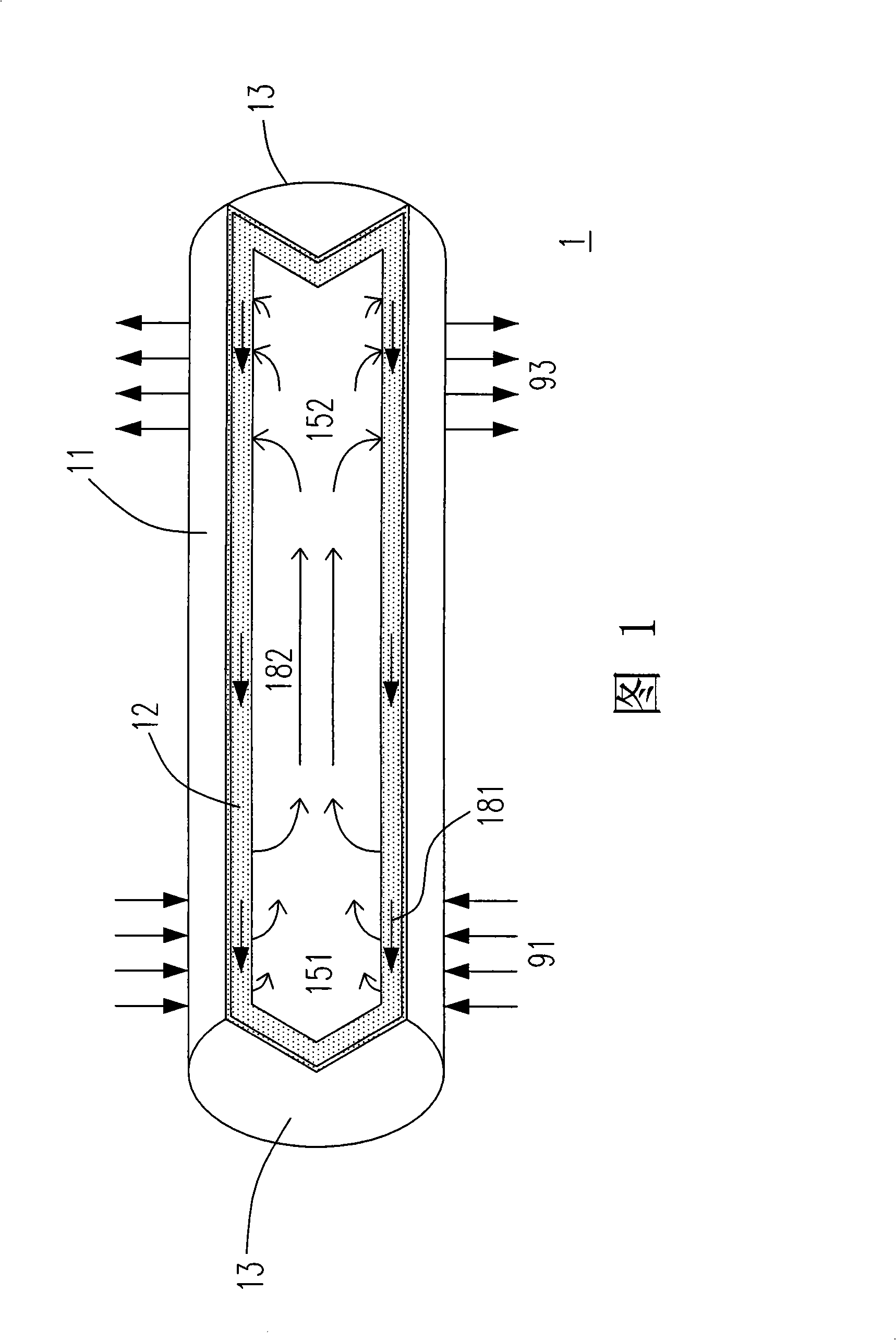
technical field [0001] The invention relates to a heat dissipation system, in particular to a heat pipe heat dissipation system comprising a flat plate evaporator. Background technique [0002] Thermal management is a necessary and challenging issue in various fields, such as the stabilization of permafrost, cooling of electronic equipment, and space vehicles. Among the many heat management methods, heat pipe (Heat Pipe) is a commonly used method. A heat pipe is a two-phase heat conduction device that conducts heat efficiently and effectively. [0003] Please refer to FIG. 1 , which is a schematic diagram of a conventional heat pipe device. In Fig. 1, the heat pipe 1 is mainly composed of a tube shell 11, a capillary structure (Wick Structure) 12 and an end cap 13, and its interior is maintained at a low pressure state, and an appropriate amount of low-boiling liquid 181 is placed in it. Liquids evaporate easily due to their low boiling points. The capillary structure co...

Claims


Application Information

Patent Timeline
Patent Type & Authority Applications(China)
IPC IPC(8): F28D15/04H05K7/20
Inventor 张晏铭简国祥
Owner IND TECH RES INST
Why Eureka
Eureka Blog
Learn More