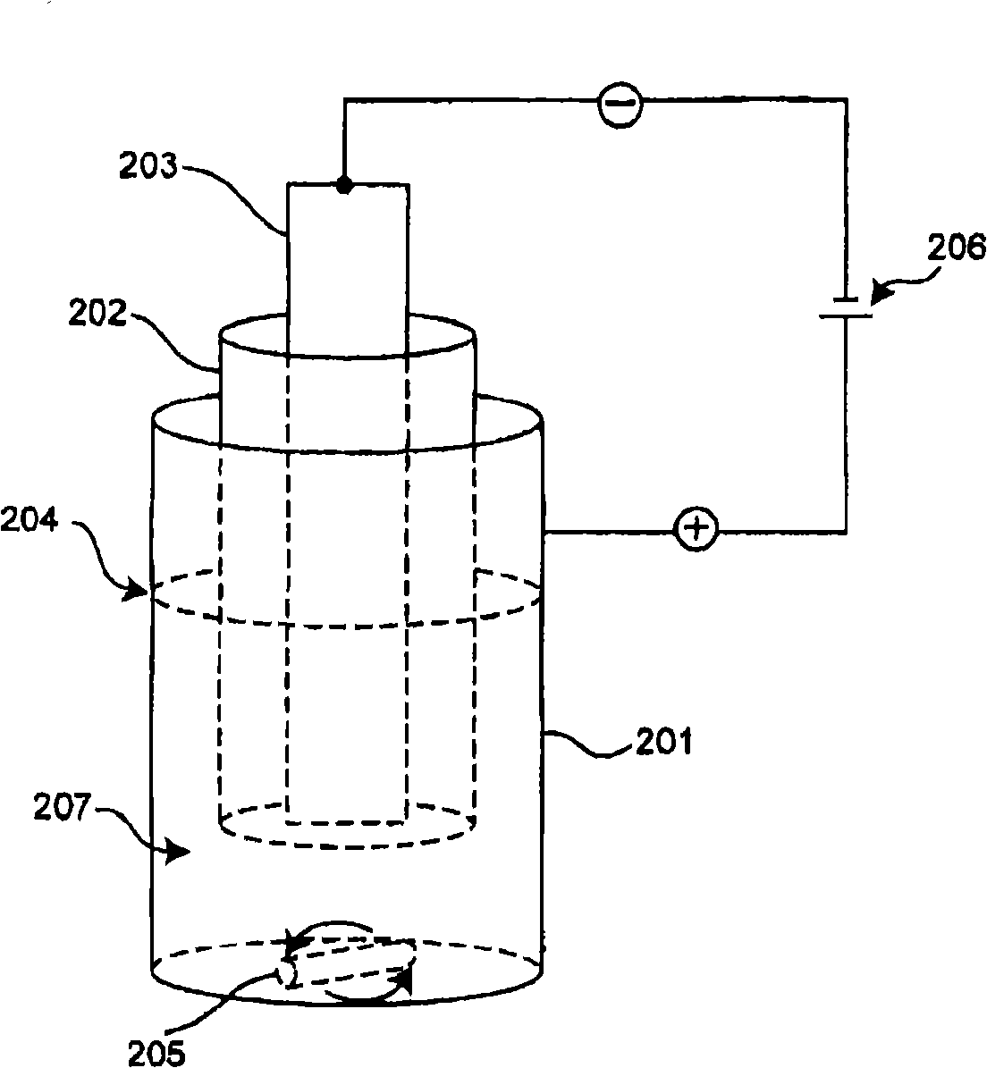
Method for forming electrodeposition coating
An electrodeposition, cation electrodeposition technology, applied in electrolytic coatings, electrophoretic coatings, coatings, etc., can solve the problems of pores, arc craters, bad appearance, etc., and achieve the effect of reducing the generation of pores and excellent appearance.
- Summary
- Abstract
- Description
- Claims
- Application Information
AI Technical Summary
Problems solved by technology
Method used
Image
Examples
preparation example Construction
[0076] 【051】 Preparation of Electrodeposition Coating Composition
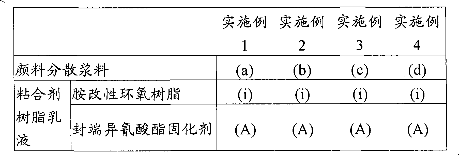
[0077] The electrodeposition coating composition in the present invention can be prepared by dispersing a binder resin emulsion, a pigment dispersion slurry, and optionally a catalyst in an aqueous medium. The binder resin emulsion includes an amine-modified epoxy resin (1) and a blocked isocyanate curing agent (2).
[0078] [052] The binder resin emulsion can be prepared by a conventional method. A preferred method of preparation involves mixing an amine-modified epoxy resin (1), a blocked isocyanate curing agent (2) and an aqueous medium containing a neutralizing acid to emulsify the binder resin. The neutralizing acid is an acid that neutralizes the amine-modified epoxy resin and improves the dispersibility of the binder resin emulsion. Neutralizing acids are inorganic or organic acids, such as hydrochloric acid, nitric acid, phosphoric acid, formic acid, acetic acid or lactic acid.
[0079] [053] When...
preparation Embodiment 1
[0096] Preparation of amine-modified epoxy resin (i)
[0097] In a flask equipped with a stirrer, cooling tube, nitrogen introduction tube, thermometer and dropping funnel, add 940 parts of liquid epoxy resin, 61.4 parts of methyl isobutyl ketone (here, abbreviated as MIBK) and 24.4 parts parts of methanol. After the temperature of the reaction mixture was raised from room temperature to 40° C., 0.01 parts of dibutyltin laurate and 21.75 parts of toluene diisocyanate (here, abbreviated as TDI) were added. The mixture was reacted at 40 to 45°C for 30 minutes. The reaction was continued until the absorption peak based on the isocyanate group disappeared.
[0098] [068] 82.0 parts of bisphenol A polyoxyethylene ether and 125.0 parts of diphenylmethane-4,4'-diisocyanate were added to the above reaction product. The reaction is carried out at 55°C to 60°C and the reaction is continued until the absorption peak based on the isocyanate group disappears in IR spectrum detection. ...
preparation Embodiment 2
[0101] Preparation of blocked polyisocyanate curing agent (A)
[0102] Add 1330 parts of crude MDI, 276.1 parts of MIBK and 2 parts of dibutyltin laurate to the reaction vessel, heat the mixture until 85 to 95°C, and then add 1170 parts of caprolactam in ethylene glycol mono Butyl ether solution (equivalent ratio of 20 / 80). After the dropwise addition was complete, the mixture was warmed to 100°C and maintained at this temperature for 1 hour. After confirming that the absorption peak based on the isocyanate group disappeared in IR spectrum detection, 347.6 parts of MIBK were added to obtain a blocked polyisocyanate curing agent.
PUM
 Abstract
Description
Claims
Application Information
 - R&D
- Intellectual Property
- Life Sciences
- Materials
- Tech Scout
- Unparalleled Data Quality
- Higher Quality Content
- 60% Fewer Hallucinations
Browse by: Latest US Patents, China's latest patents, Technical Efficacy Thesaurus, Application Domain, Technology Topic, Popular Technical Reports.
© 2025 PatSnap. All rights reserved.Legal|Privacy policy|Modern Slavery Act Transparency Statement|Sitemap|About US| Contact US: help@patsnap.com


