
Checking system light source stray illumination device

A technology for detection systems and lighting devices, applied in lighting devices, components of lighting devices, cooling/heating devices of lighting devices, etc., can solve the problems of shortened exposure time and insufficient light of line scanning CCD

Inactive Publication Date: 2008-10-22
IND TECH RES INST
View PDF6 Cites 14 Cited by
  • Summary
  • Abstract
  • Description
  • Claims
  • Application Information

AI Technical Summary

Problems solved by technology

However, because the line-scan CCD scans an image by multiple scanning lines to form a scanning surface, the exposure time of the CCD between lines and lines becomes shorter during high-speed scanning, thereby producing a line-scan CCD. Into the problem of insufficient light

Method used


Image

  • Checking system light source stray illumination device
  • Checking system light source stray illumination device
  • Checking system light source stray illumination device

Examples


Embodiment Construction

[0024] The above and other technical features and advantages of the present invention will be described in more detail below in conjunction with the accompanying drawings.

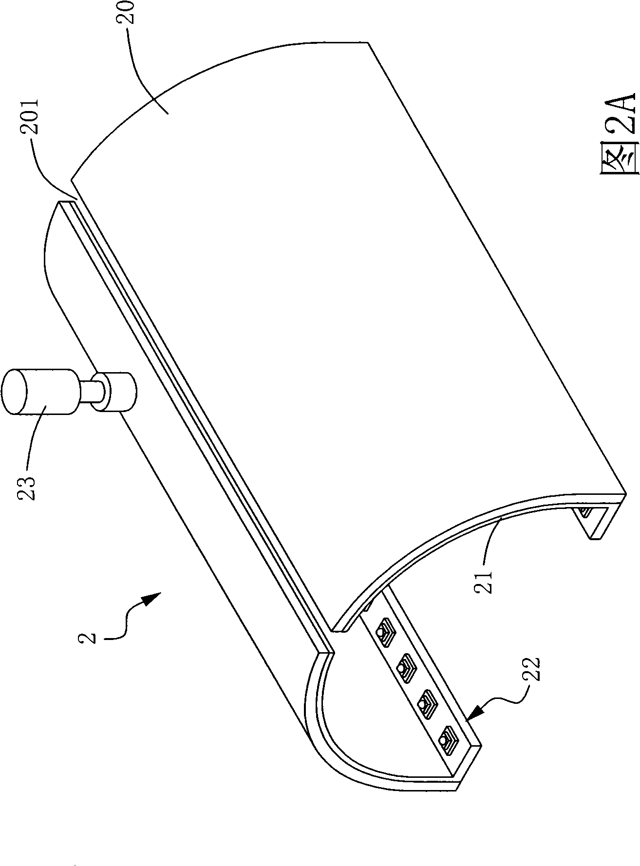
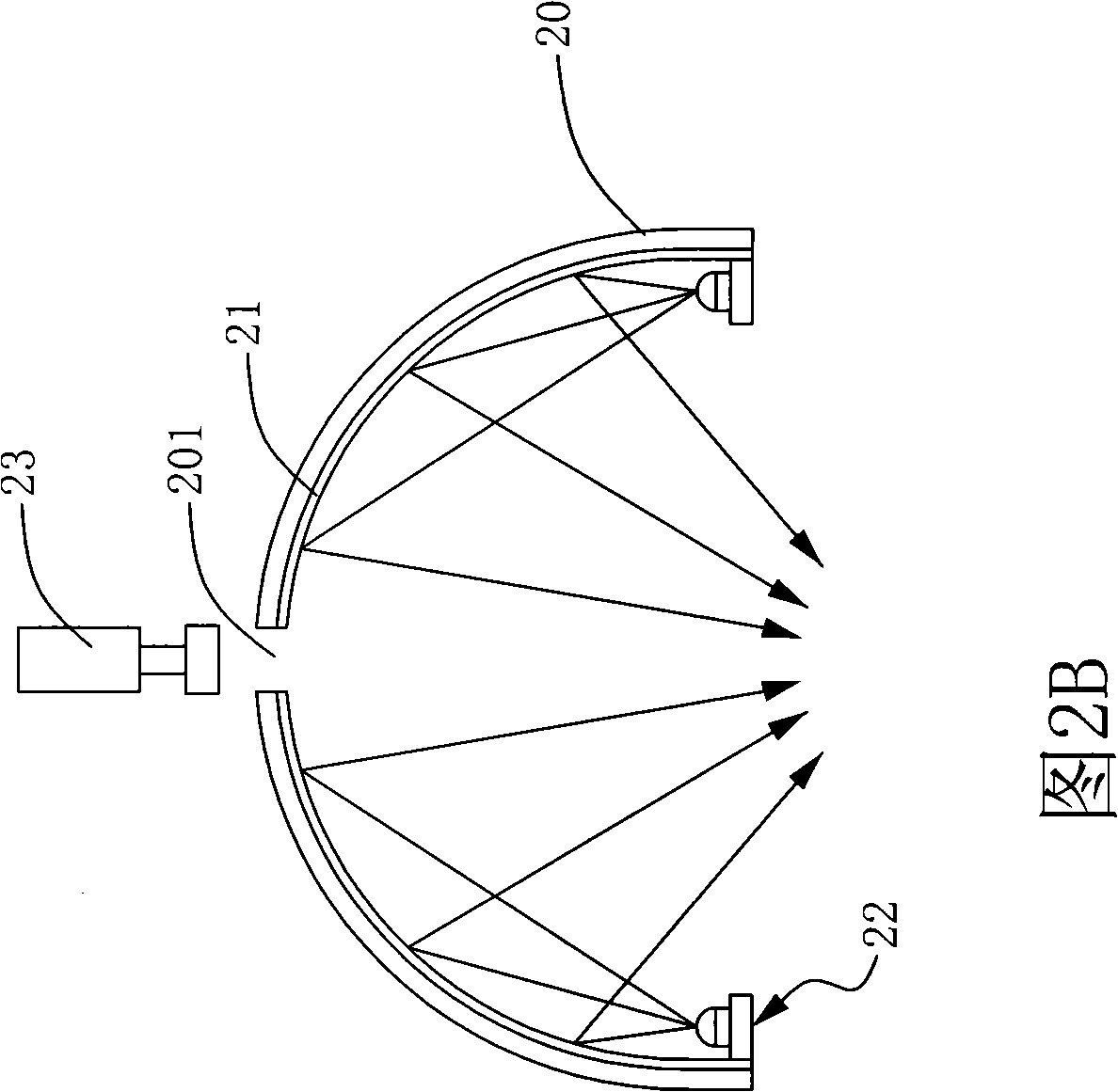
[0025] Please refer to FIG. 2A and FIG. 2B , which are schematic diagrams of a preferred embodiment of the light source scattering illumination device of the detection system of the present invention. In FIG. 2A , the light source diffusion lighting device 2 has a reflective cover 20 , a Teflon (Poly tetrafluoroethylene, PTEF) diffusion layer 21 and at least one light emitting device 22 . In this embodiment, the reflective cover 20 is a semi-cylindrical cover, and a slot 201 is defined above the cover 20, and the slot 201 is a linear slot. An image capture device 23 is disposed above the slot 201 , and the image capture device 23 in this embodiment is a line-scan photocoupler device (line-scan CCD).

[0026] As shown in Figure 2B, on the inner wall surface of the reflective cover 20, the Teflon scattering...


PUM

PropertyMeasurementUnit
Poweraaaaaaaaaa

Abstract

The present invention discloses a light source scattering illumination device for a detecting system. The device comprises a reflection cover body, a Teflon scattering layer and at least one luminous device. The reflection cover body is provided with a slotted hole. The Teflon (PTFE) scattering layer is arranged on the inner wall of the reflection cover body. The at least one luminous device is arranged inside the reflection cover body. The luminous device is further provided with a plurality of luminous bodies which are arranged in the form of arrays to provide a light source. With the Teflon scattering layer in the present invention, perfect scattering efficiency can be provided and uniform scattered light can be generated. Through selecting high power light emitting diodes as a luminous source, the luminous device also can provide perfect light strength so that the light source scattering device can generate high brightness and the uniform scattered light to solve the problem that the detecting system is insufficient in illumination strength.

Description

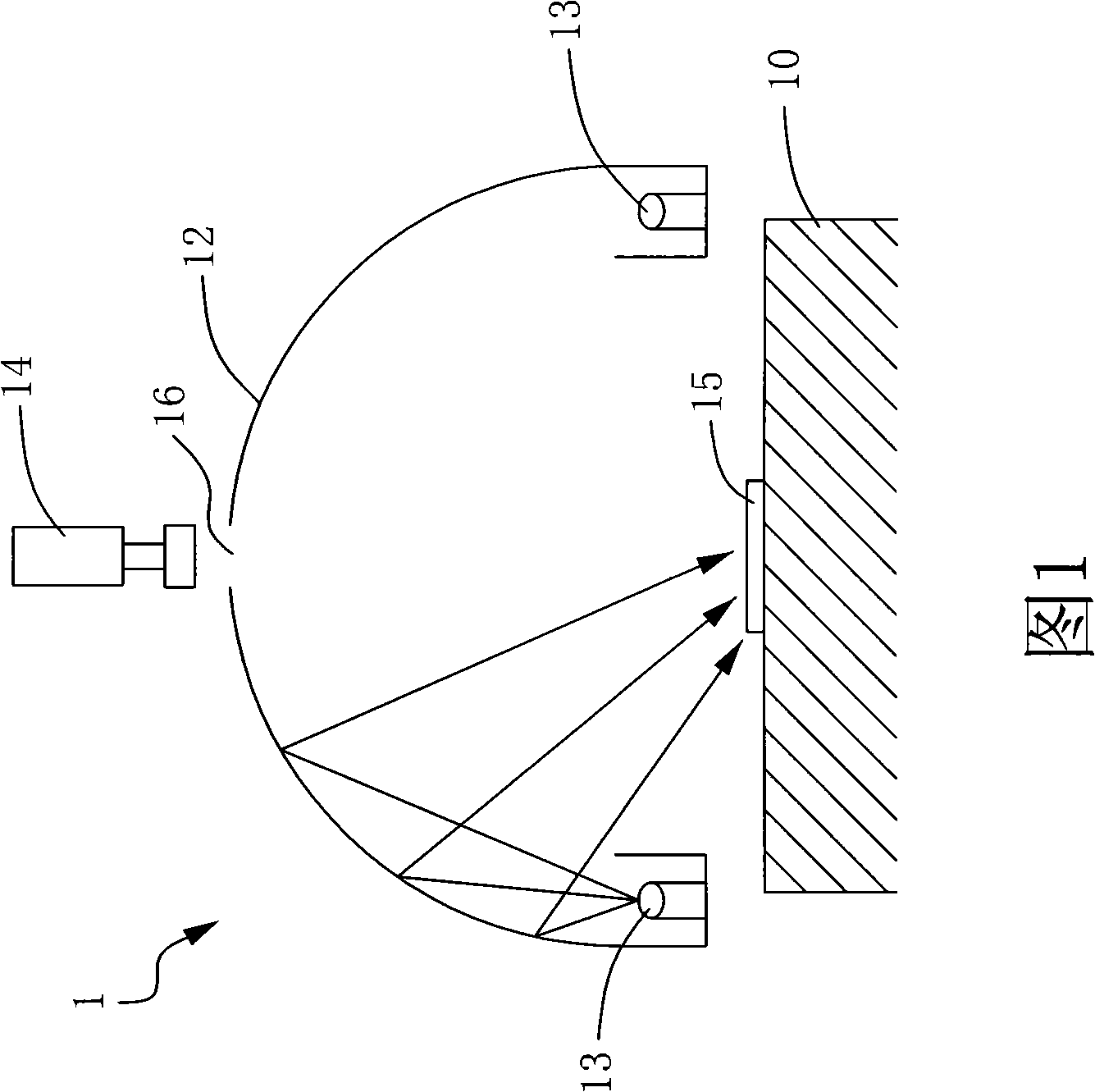
technical field [0001] The present invention relates to a diffused lighting device, in particular to a light source scattering detection system which uses Teflon material as a diffuser film and uses an array of light sources to increase the amount of light source to achieve uniform scattered light and improve illumination intensity. lighting fixtures. Background technique [0002] Inspection procedures play a very important role in the manufacturing process of products. Use the detection device to capture the image of the object to be tested, and use automatic or manual judgment to identify the product, such as: panel, printed circuit board or chip defects, such as: impurities, short circuit or open circuit, scratches, etc. Defects, in order to do a good job in quality control. [0003] Please refer to FIG. 1 , which is a schematic diagram of a diffuse lighting device disclosed in the prior art. The device 1 has a base 10 , a reflective cover 12 , a light emitting device ...

Claims


Application Information

Patent Timeline
IPC IPC(8): F21S2/00G01N21/88F21V3/04F21V3/02F21V29/00F21K9/20F21V29/76F21V29/83
Inventor 涂钟范王俊杰石宇森
Owner IND TECH RES INST
Learn More