
Adaptive digital DC/DC control method and converter with fast dynamic response

A control method and dynamic response technology, applied to controllers with specific characteristics, electric controllers, conversion equipment with intermediate conversion to AC, etc., can solve the problem of not being able to suppress overshoot, large reverse impulse voltage, and output oscillation at the same time. and other problems, to meet the requirements of dynamic response speed and adjustment effect, ensure steady-state performance, and improve the effect of dynamic response speed

Inactive Publication Date: 2008-10-15
SHENZHEN ACAD OF AEROSPACE TECH
View PDF0 Cites 21 Cited by
  • Summary
  • Abstract
  • Description
  • Claims
  • Application Information

AI Technical Summary

Problems solved by technology

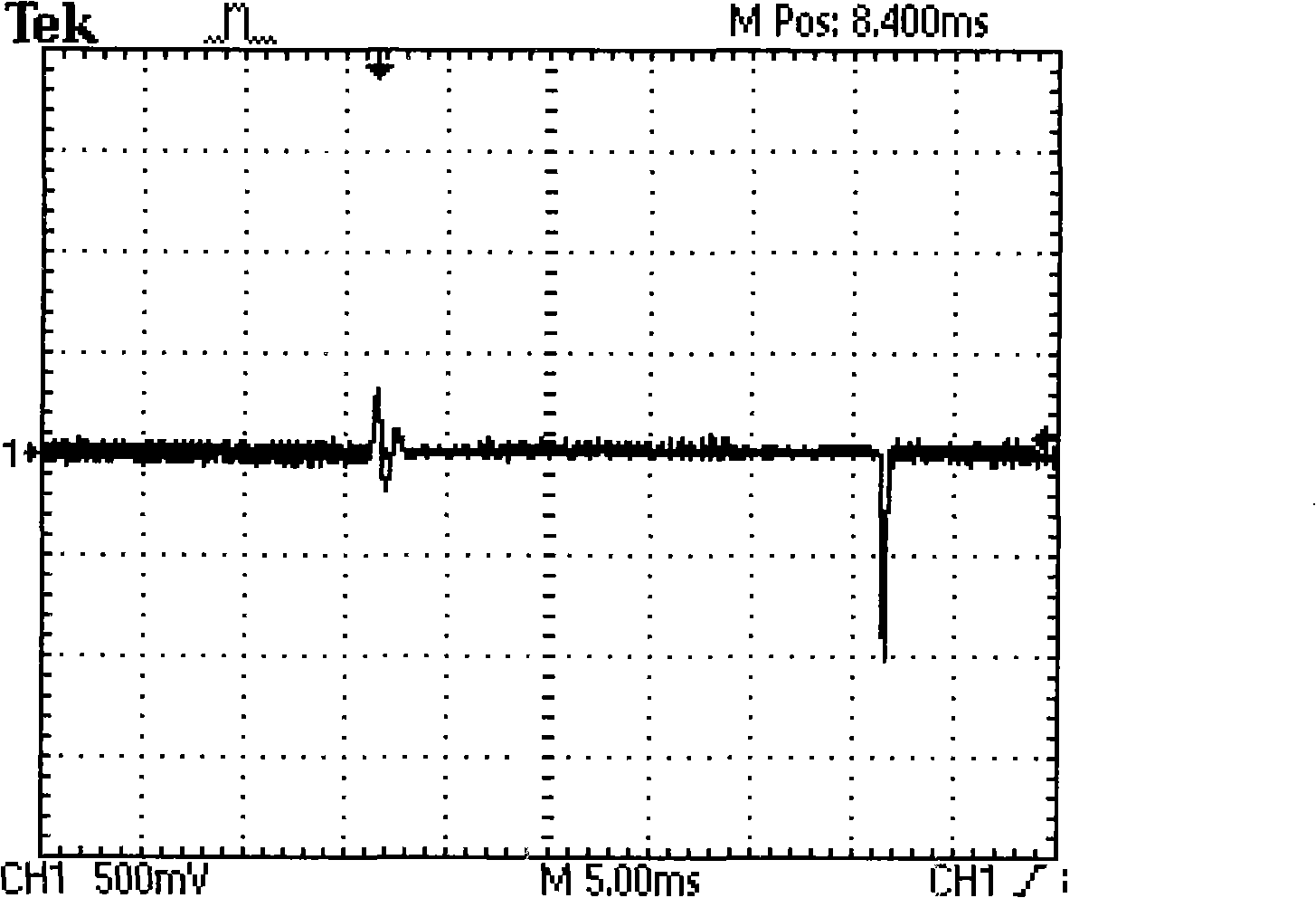
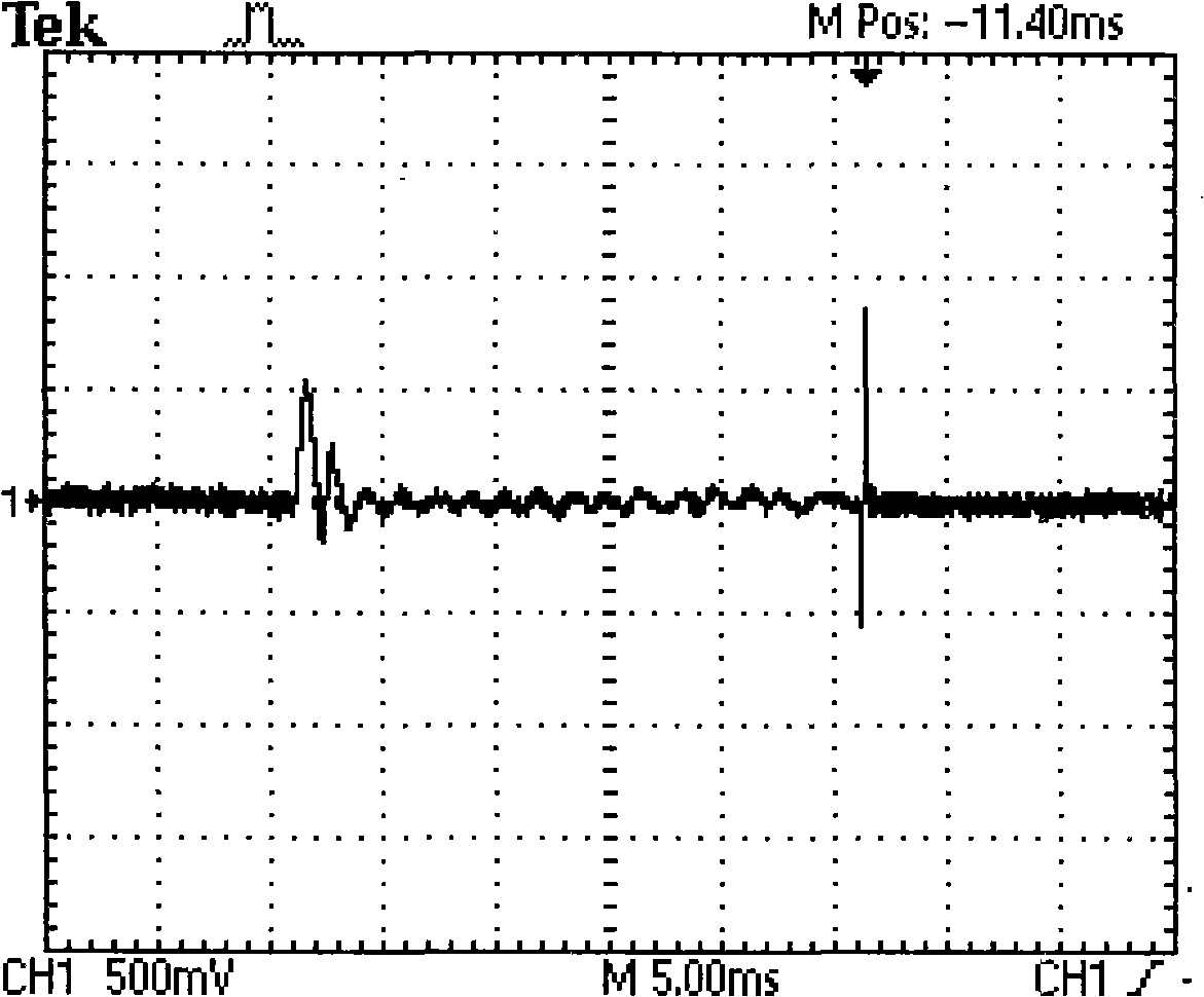
[0010] In order to solve the described acceleration algorithm that exists in the prior art, the overshoot amplitude or the sink amplitude of the output voltage can only be suppressed, and the overshoot in both directions cannot be suppressed at the same time; when performing overshoot and undershoot processing at the same time, the error There is an overlapping area in the threshold, which will lead to the cycle of overshoot and sag, and the output will oscillate; and because the suppression of overshoot (or sag) and recoil always restrict each other and contradict each other, the smaller the threshold value of the absolute value of the error is set, The better the suppression effect on the overshoot (or sag), but the greater the reverse impulse voltage and other technical problems, the present invention provides an adaptive digital DC / DC control method with fast dynamic response

Method used


Image

  • Adaptive digital DC/DC control method and converter with fast dynamic response
  • Adaptive digital DC/DC control method and converter with fast dynamic response
  • Adaptive digital DC/DC control method and converter with fast dynamic response

Examples


specific Embodiment

[0038] Specific embodiment: In view of the dynamic response of -12V all the way at 10% to 50% load switching, the control algorithm with better steady-state performance is described as follows:

[0039] U(n)=1.051U(n-1)-0.0507U(n-2)+11.61e(n)-21.81e(n-1)+10.24e(n-2) The better dynamic control algorithm is:

[0040] U(n)=U(n-1)+19.84e(n)-36.21e(n-1)+16.53e(n-2)

[0041] The principle of switching between the two sets of parameters is: when the undershoot amplitude of the output voltage exceeds the set value of 187mV, switch to a parameter with better dynamic performance. When the error becomes negative, it is considered to have entered a steady state, and it is detected twice in a row. When the error changes alternately between positive and negative, it is considered that the steady state has been reached, exit the fast parameter, and switch to the parameter with better steady state performance.

[0042] The present invention has an adaptive digital DC / DC control method with fast d...


PUM


Abstract

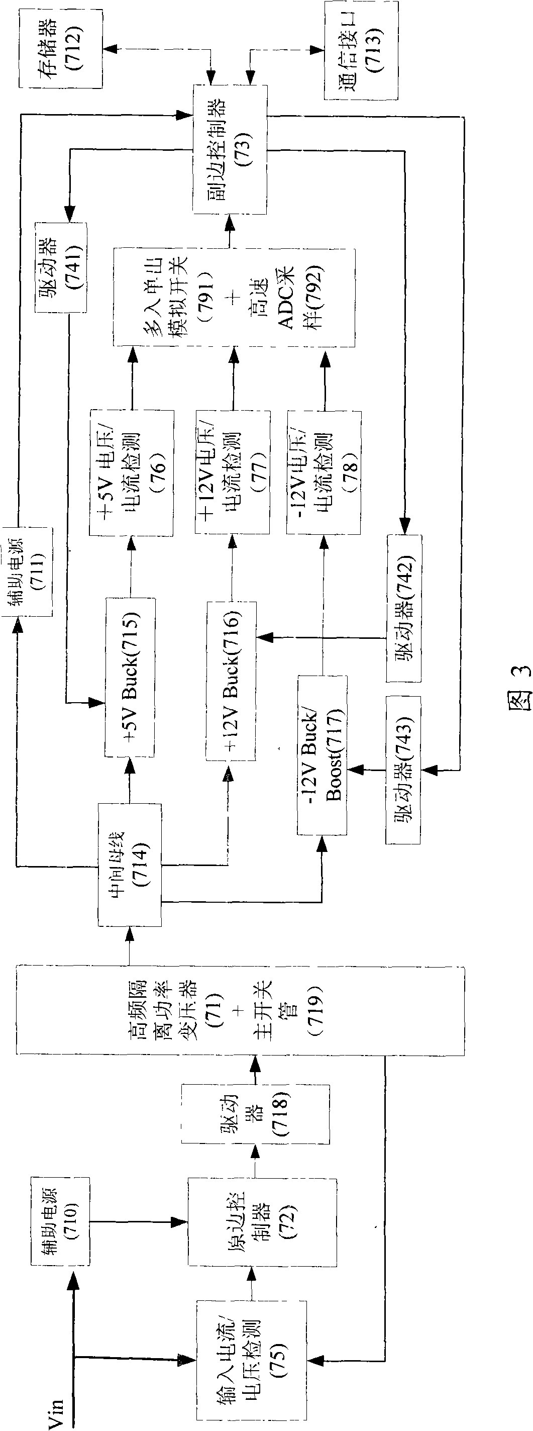
The invention relates to a self-adaptive digital DC / DC control method which has fast dynamic response and a converter. The self-adaptive control method related by the invention is implemented in a secondary side controller. In the control method, error detected is positive (negative) when sag (uprush) happens to an output voltage, and a first PID with good steady-state characteristics is switched to a second PID with good dynamic characteristics when the absolute value of the error exceeds a preset threshold value, the output voltage begins to enter a steady state when the error turns to be negative (positive), and the second PID is switched to the first PID when alternative changes between positive and negative errors are continuously detected, for which a steady state is deemed to be realized. The circuit structure of the DC / DC converter comprises a main power topology, an isolating transformer, a primary side controller, the secondary side controller, a driving circuit, a voltage and current detecting channel, a feedback and sampling channel, a primary side assisting source, a secondary side assisting source, a parameter memorizer and a communication interface. The control method of the invention has reasonable design and the converter is simple and practical.

Description

Technical field [0001] The present invention relates to a digital DC / DC converter thereof and a control technique thereof, and a digital DC / DC converter having an adaptive change control algorithm, increasing the dynamic response speed of the output voltage dynamic response. Background technique [0002] The DC / DC converter is typically a terminal power supply for various types of electrical devices, so its dynamic and steady state directly affect the working state of the load. The dynamic response and steady state characteristics of the system are contradictory. The faster the dynamic response speed of the system, the adaptability of the load or input change, at which time the input error of the regulator is large, the adjustment effect is fast, but the system over-tuning is too large to cause system oscillation, steady state characteristics; Conversely, the better steady-state performance, the dynamic response of its dynamic response is often difficult to meet the require...

Claims


Application Information

Patent Timeline
IPC IPC(8): H02M3/28G05B11/42
Inventor 张东来冯永代守仑张华
Owner SHENZHEN ACAD OF AEROSPACE TECH
Learn More