
Elementary inertia meter

A basic inertia, tester technology, applied in the testing of machine/structural components, static/dynamic balance testing, instruments, etc., can solve the problem of poor data accuracy and repeatability of measurement results, inability to meet the requirements of technical indicators, and difficult assumptions. Establishment and other issues, to achieve the effects of good measurement accuracy and repeatability, light weight, and reduced labor intensity

Inactive Publication Date: 2008-10-15
周申生
View PDF0 Cites 7 Cited by
  • Summary
  • Abstract
  • Description
  • Claims
  • Application Information

AI Technical Summary

Problems solved by technology

[0014] 1. After the flywheel is increased or decreased, the wind resistance of the flywheel rotation and the body resistance of the background body after the increase or decrease of the flywheel change, which makes the assumption of the basic inertia calculation formula difficult to establish, and the accuracy and repeatability of the measurement results are poor, and cannot meet the relevant technical indicators requirements
[0015] 2. To detect the basic inertia, it is necessary to increase or decrease the inertia flywheel, which cannot be realized in the field of equipment use
[0016] 3. It is difficult to calculate the equivalent car mass of the moment of inertia of the mechanical flywheel

Method used

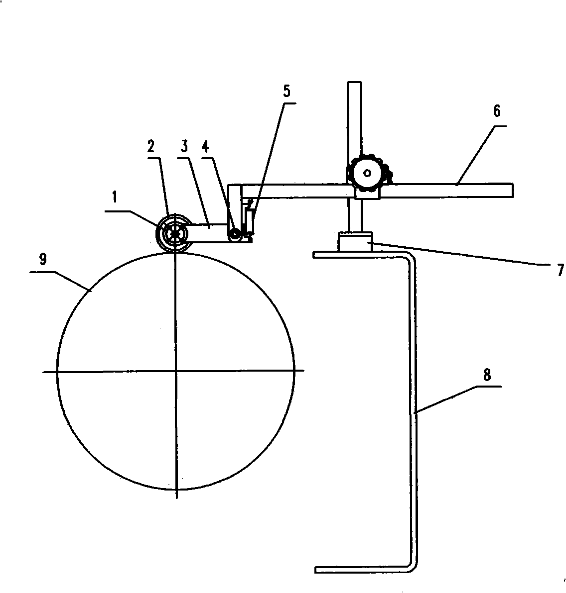
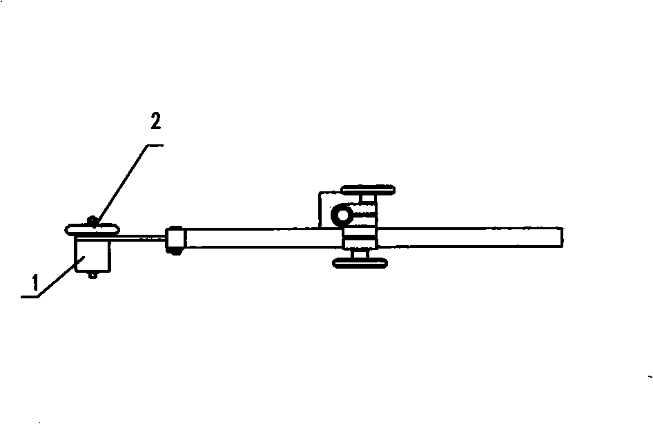

Image

  • Elementary inertia meter
  • Elementary inertia meter
  • Elementary inertia meter

Examples


example

[0026] Fully preheat the chassis dynamometer or the equipment to be tested according to the requirements of the equipment manual, and then proceed as follows:

[0027] 1. Drive the drum at a speed of 56km / h, and perform constant force F in the speed range of (48~16)km / h 1 =Sliding test at 1170N, the upper station records the sliding time Δt 1 (s) and the average value of the measured resistance F1(N), the measured start and end sliding speed difference ΔV 1 .

[0028] 2. Drive the drum at a speed of 56km / h, and perform constant force F in the speed range of (48~16)km / h 1 = 0N when sliding test, the upper station record the sliding time Δt 2 (s) and the average value of the measured resistance F2(N), the measured start and end sliding speed difference ΔV 2 .

[0029] 3. The upper computer obtains DIW according to the calculation formula

[0030] DIW=(F1-F2) / (ΔV 1 / Δt 1 -ΔV 2 / Δt 2 )

[0031] 4. Repeat the above measurement two more times, and find the average of the ...


PUM


Abstract

The invention provides a fundamental inertia tester, comprising an IGBT control casing, a speed sensor assembly and a computer, wherein, the IGBT control casing comprises a microprocessor and a high power field effect transistor, and is electrically connected with the speed sensor assembly, the computer, a force sensor on a chassis dynamometer and an electric eddy current machine; the IGBT achieves constant force control to the electric eddy current machine, measures signals transmitted from the speed sensor assembly and the force sensor through twice load coast-down of constant forces F1 and F2 respectively, and measures the speed of a roller and a medium value of actual measured resistances; and a computer program measures and controls the whole measurement process and calculates the measurement result according to the computing formula of the fundamental inertia. The fundamental inertia tester has the advantages of accurate measurement, good repetitiveness, easy operation, capability of measuring the automobile chassis dynamometer in using field and convenient portability.

Description

technical field [0001] The invention relates to a basic inertia measuring device, in particular to a basic inertia tester for an automobile chassis dynamometer. Background technique [0002] According to the national environmental protection industry standards HJ / T290-2006, HJ / T291-2006, HJ / T292-2006 and HJ / T396-2007, the basic inertia of the chassis dynamometer used for the measurement of exhaust pollutants by the working condition method is To be measured, its basic inertia should be within ±2% of the specified value, with a 1% permissible difference from the nominal value. HJ / T396-2007 stipulates that the measurement shall be carried out according to the following methods: [0003] 1. The chassis dynamometer is fully preheated, no load is applied to the chassis dynamometer, and the coasting time t1(s) of 48-32km / h is detected when the chassis dynamometer is in a normal structural state. [0004] 2. After the mechanical flywheel of the chassis dynamometer is removed, the...

Claims


Application Information

Patent Timeline
IPC IPC(8): G01M1/10
Inventor 周申生周速帆
Owner 周申生
Learn More